Introduction
This is part 4 of a blog series I’m doing to catalog my adventures through some of the programs I wrote back in 1988.
Other parts of this series, including this one are listed below.
- Disassembling my old code part 1 – Getting started with WinAPE
- Disassembling my old code part 2 – Setting screen mode & Soft 968
- Disassembling my old code part 3 – Text operations
- Disassembling my old code part 4 – Set cursor position & disc cache <—- you are here
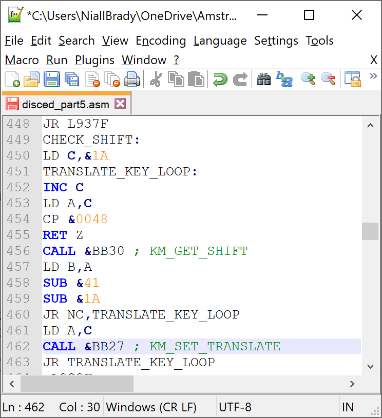
- Disassembling my old code part 5 – Get Shift key and set translate
- Disassembling my old code part 6 – Processing disc activities
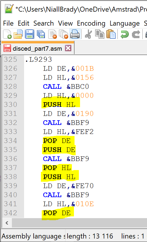
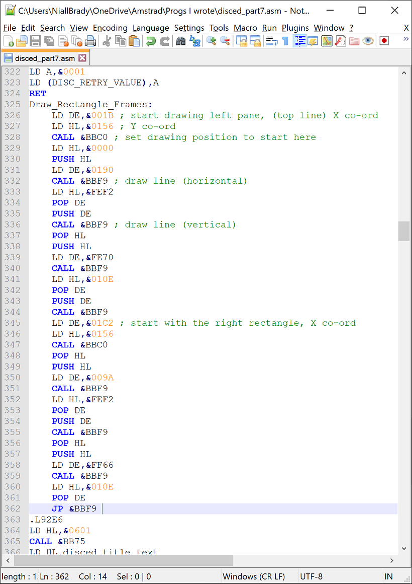
- Disassembling my old code part 7 – Drawing rectangles
- Disassembling my old code part 8 – Processing HEX in the left pane
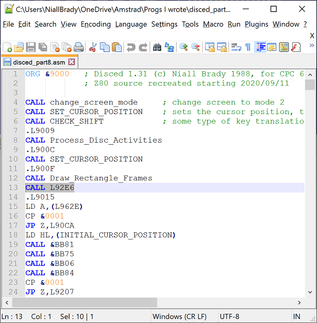
I decided that I wanted to start clearing up the beginning part of the code and make sense of the early calls that appear right at the start of the code. So that’s where today’s part begins, on the second call to label L941A.
I don’t yet know what this code does but let’s dig into it.
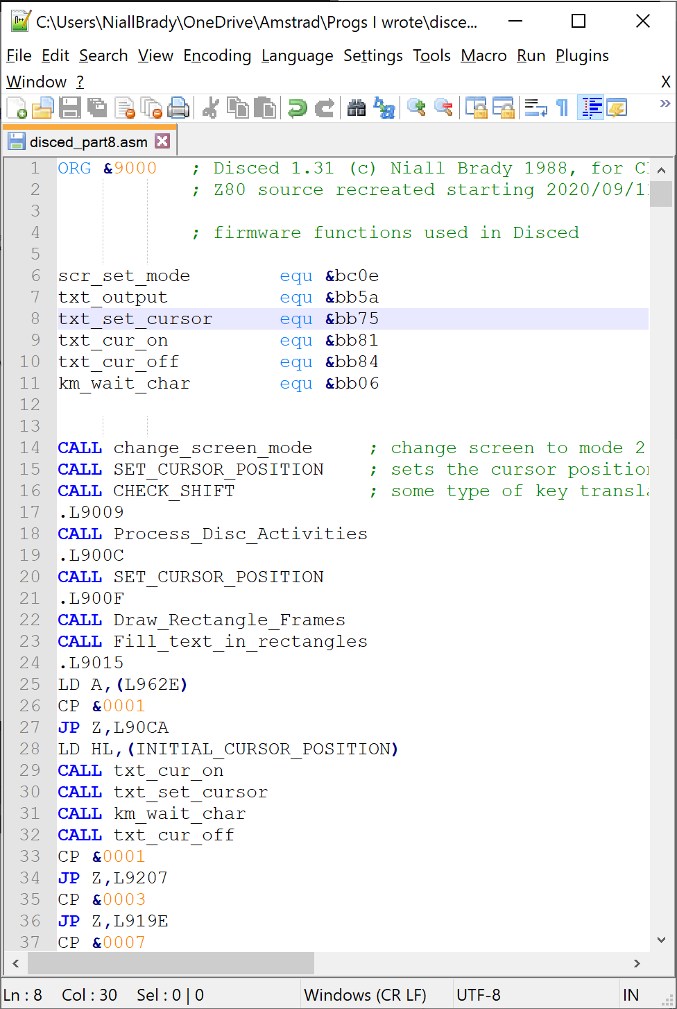
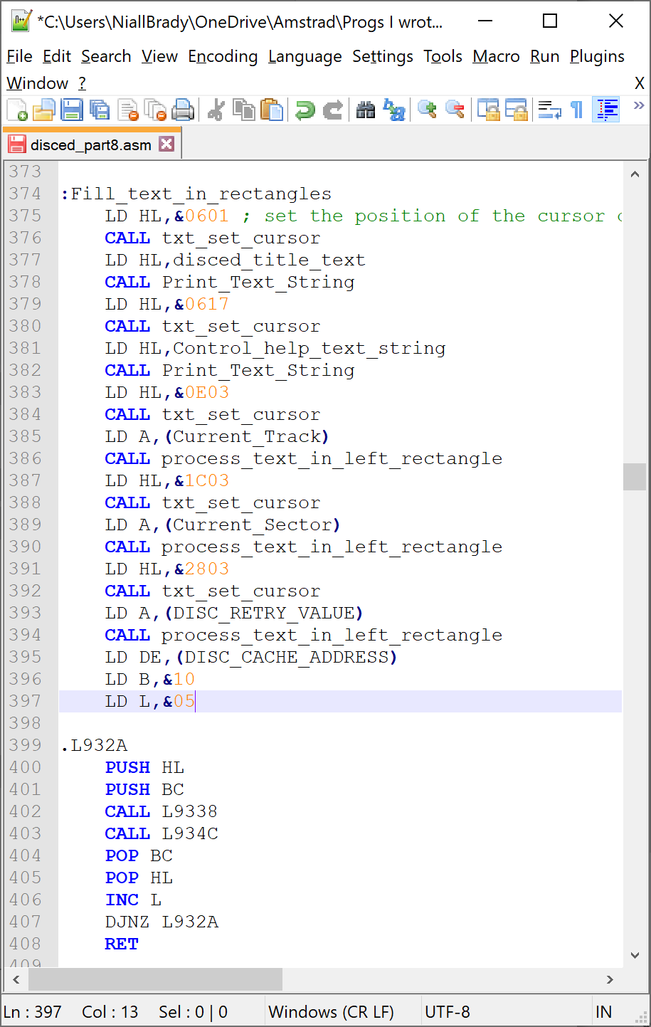
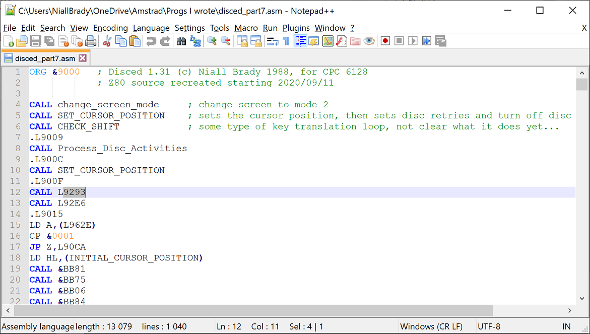
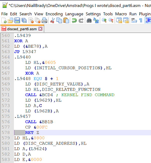
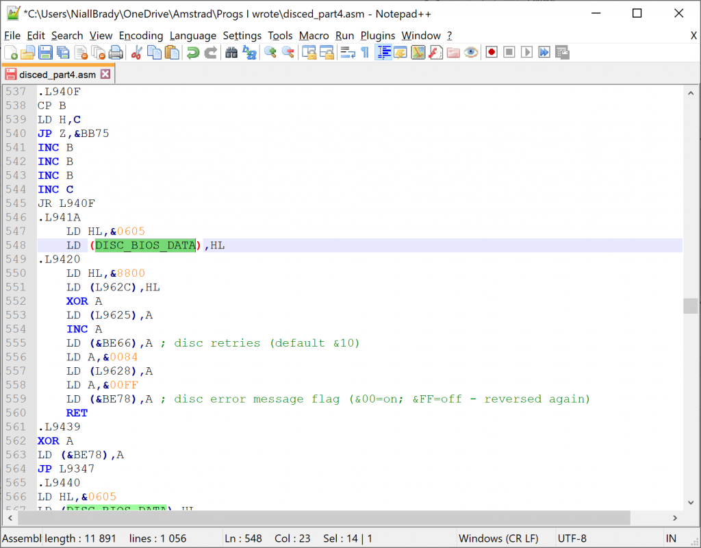
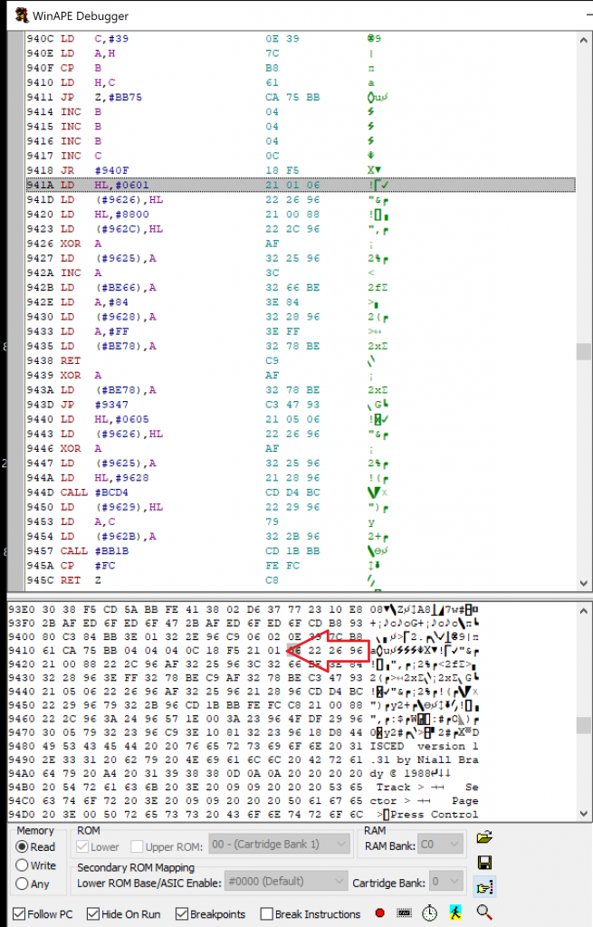
Here’s the source code in question for this particular label, it’s merely loading the HL register with an address &0605 and then loading that into another address at label &9626.
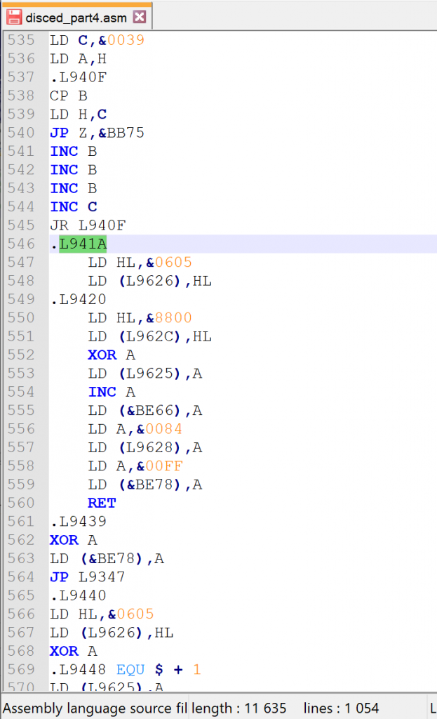
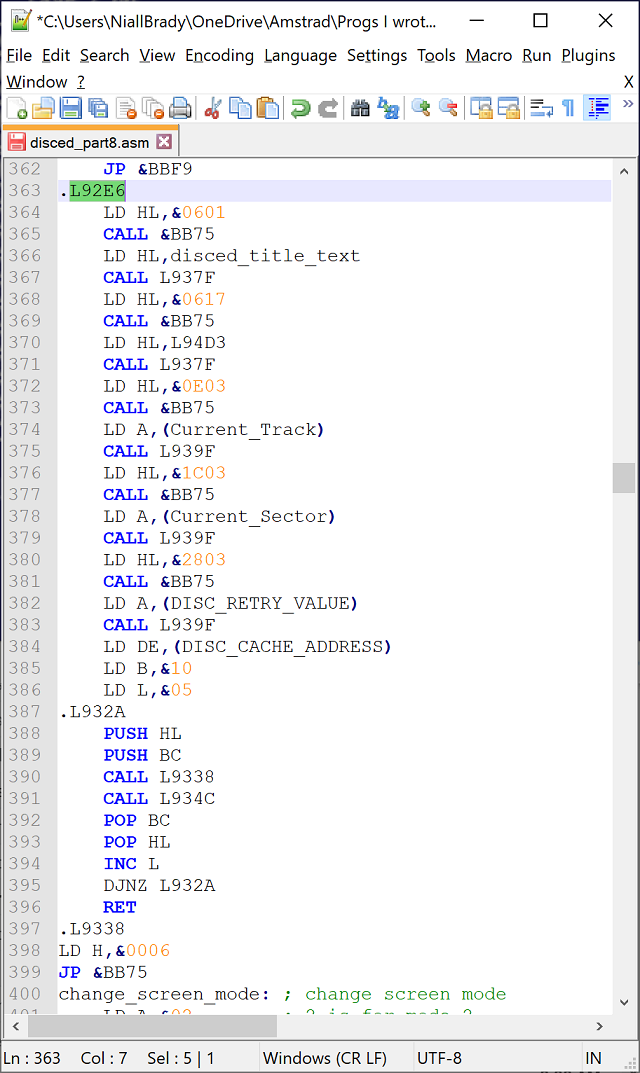
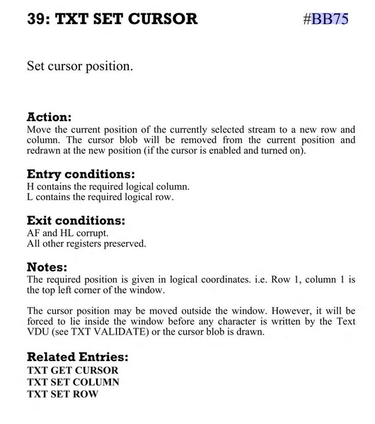
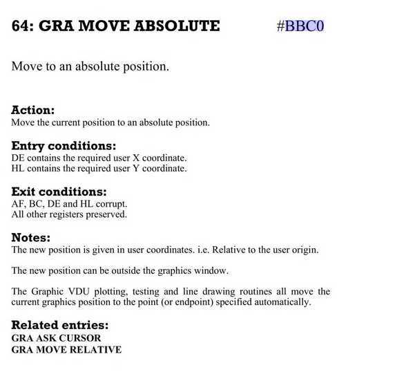
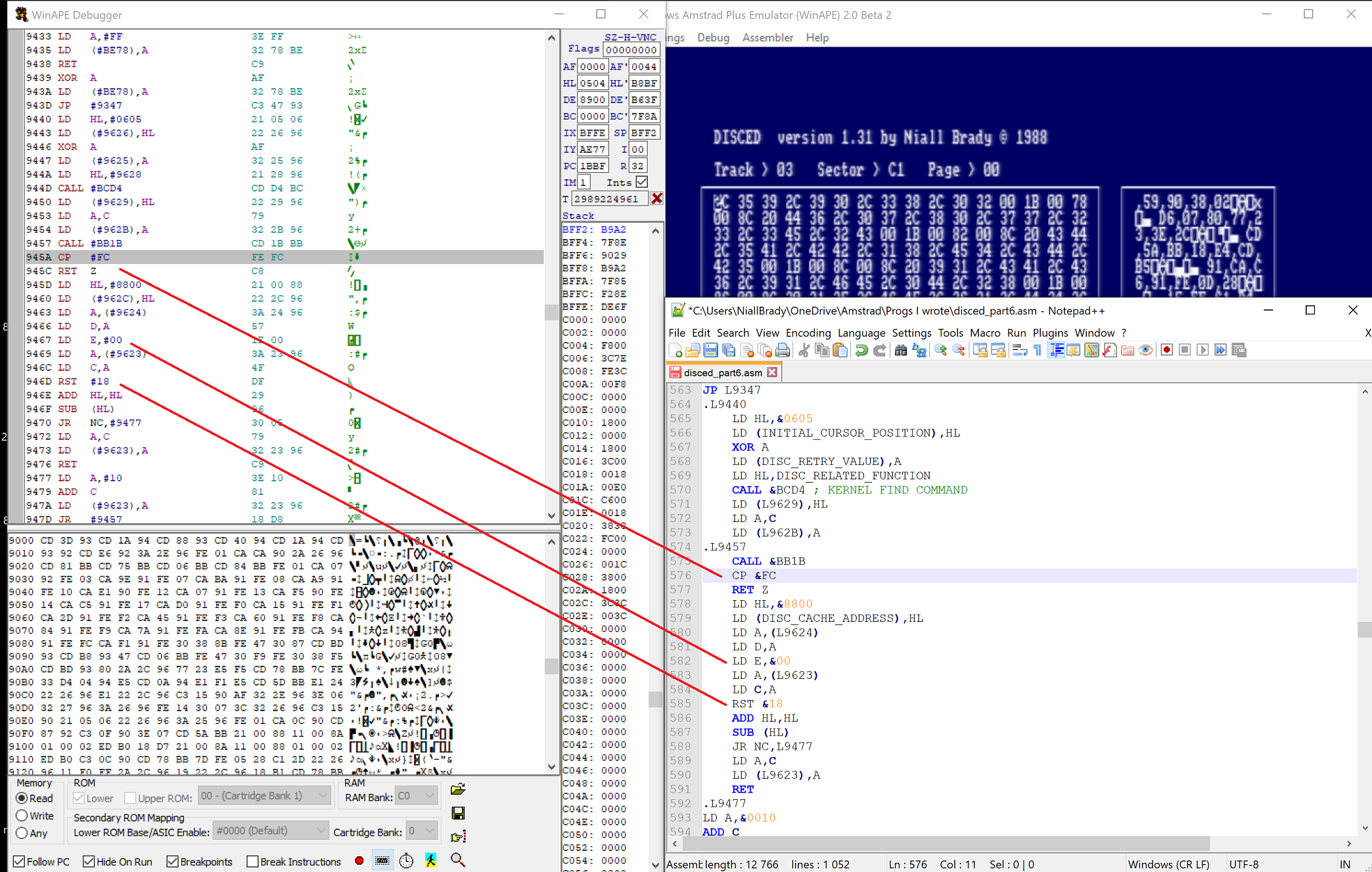
It then merges into another block of code which utilizes two firmware addresses namely:
So maybe those two firmware addresses will give me some clues as to what is happening here.
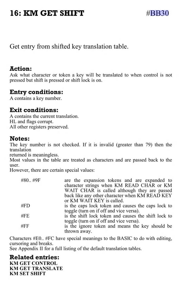
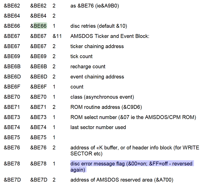
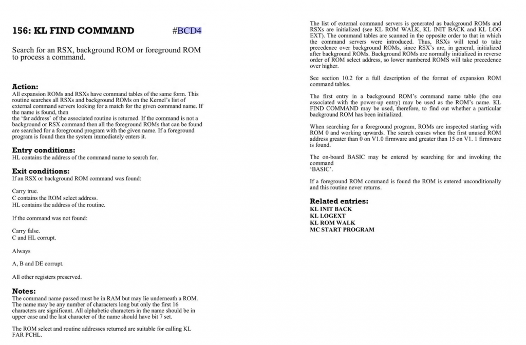
And indeed, those two addresses are important, &BE66 is for disc retries (default &10) and & BE78 is for disc error message flag (&00=on; &FF=off – reversed again) as you can see from this Amstrad CPC Firmware Guide.
So I’ve now added those comments from above into the functions (routines ? not sure what they are called in assembly) and hopefully MAXAM won’t complain about the way I’ve added these comments when I eventually try and reassemble this code.
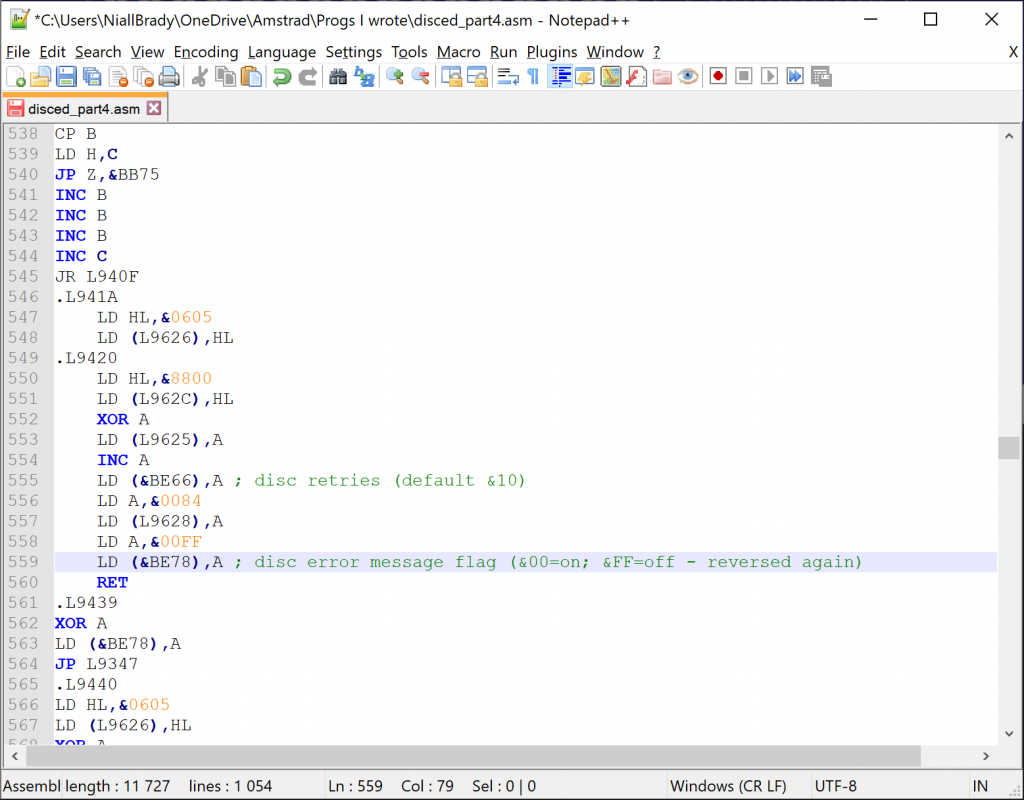
This little code block (which is made up of two blocks of code) therefore seems to disable disc error messages and set’s the disc retries to 5 (I think).
I’m just not exactly sure why I’m loading HL with &0605 and then storing that value at L9626 before it actually sets the retry and disc error message status.
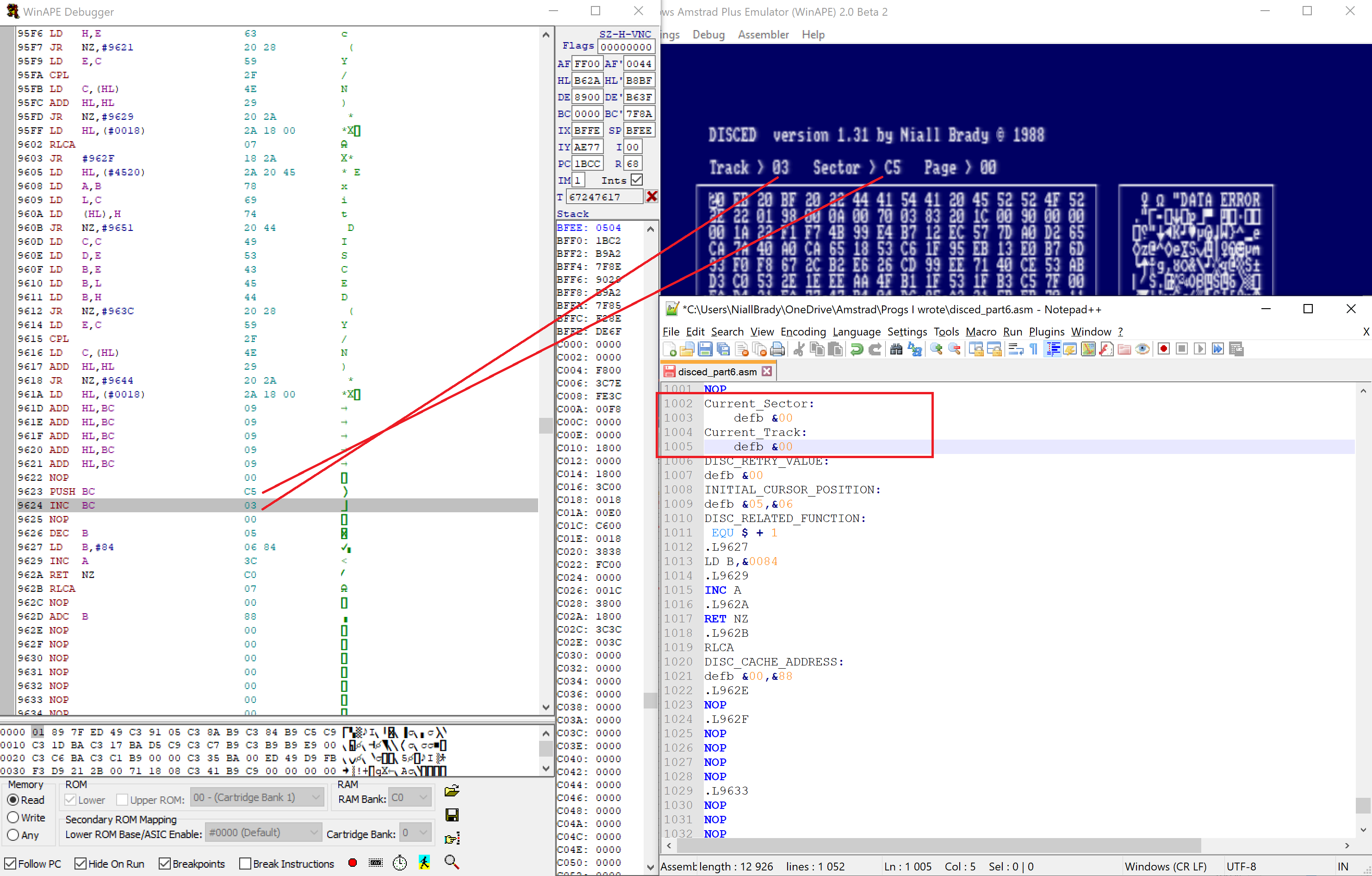
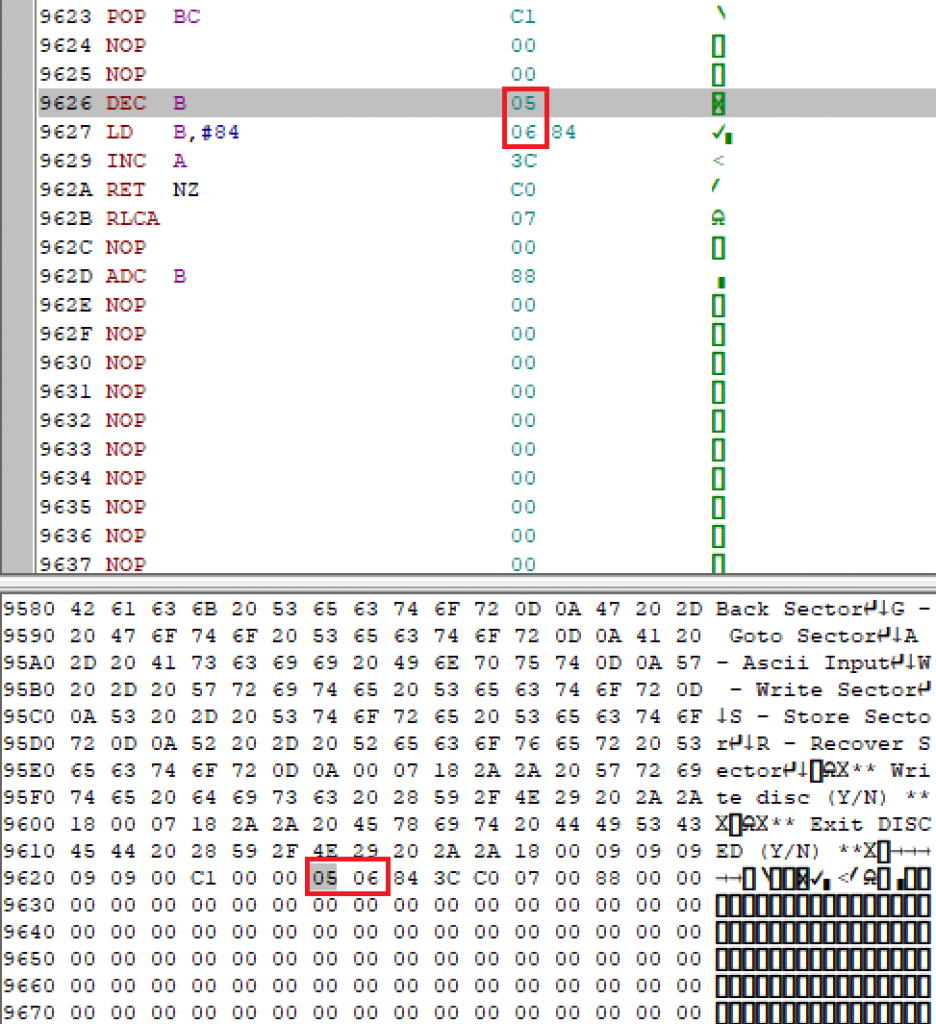
Let’s take a closer look at L9626. Doing so reveals the values &05 &06 which came from the value stored in HL above. So we can assume that these two bytes of data are important in relation to Disc bios actions, so I’ll assign this L9626 a label called DISC_BIOS_DATA: as I don’t yet know what the &05 &06 values are for.
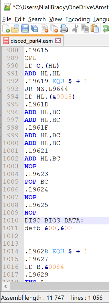
I’ll populate those two bytes in the assembly source code with blank values (&00) seeing as we’ll be poking &05 &06 into them later anyway.
So they now look like this.
And next I use notepad++’s search and replace functionality to replace all instances of L9626 with the new label.
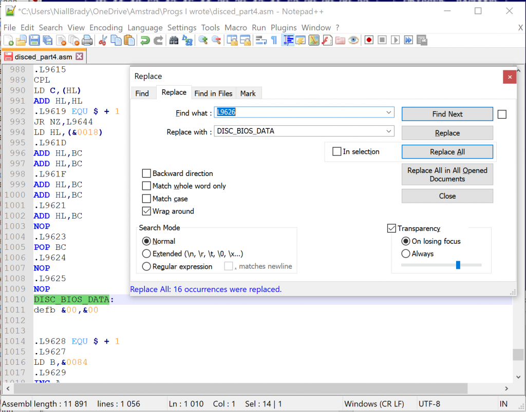
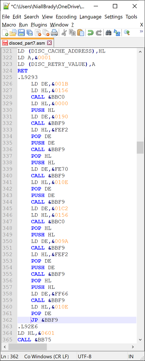
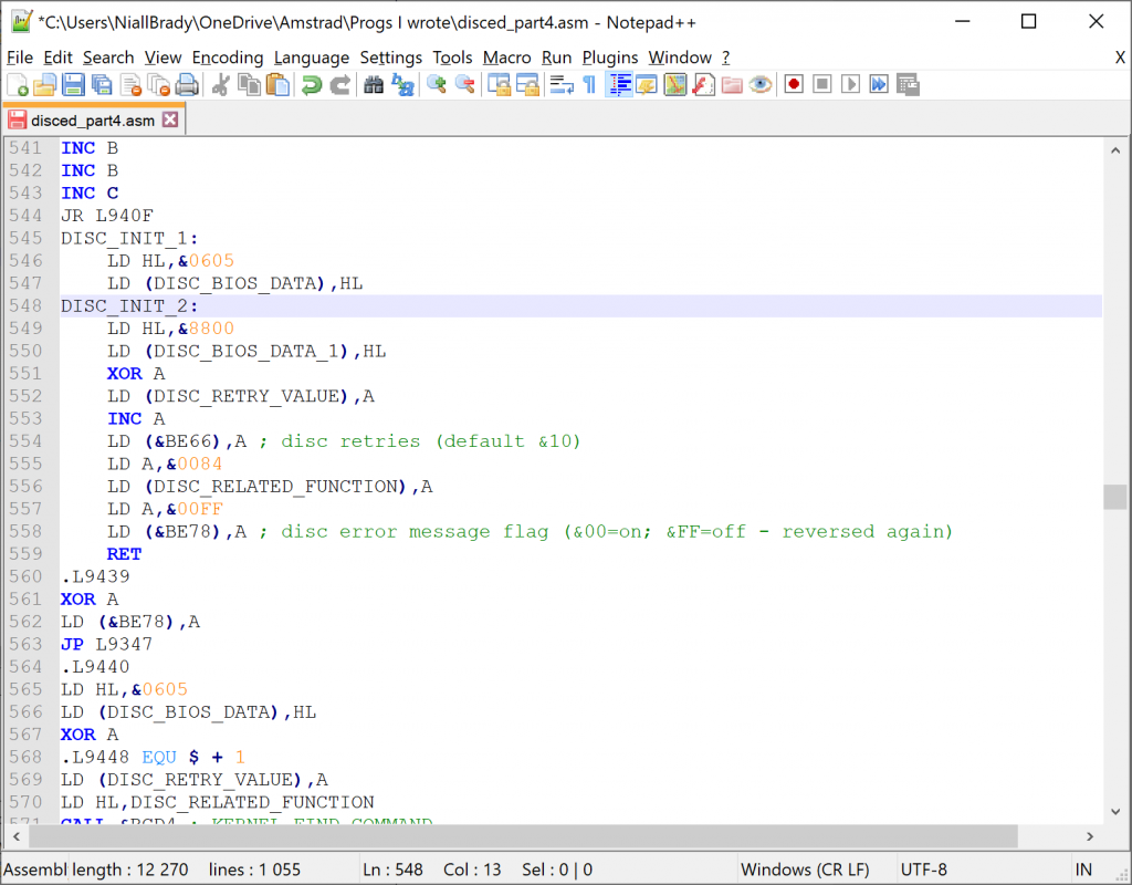
After those edits, I can see our wee block of code now looks like this.
And what’s clear here is that there are a few more areas used for temporary data storage, so for now i’ll just keep using the DISC_BIOS_DATA label but increment it by 1 each time I think it’s relevant, remembering that I’ll probably change a lot of these labels later on once I get it actually running.
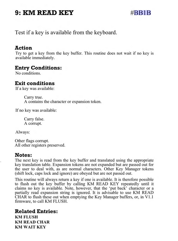
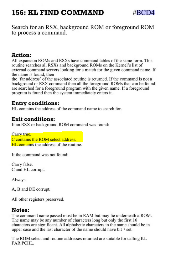
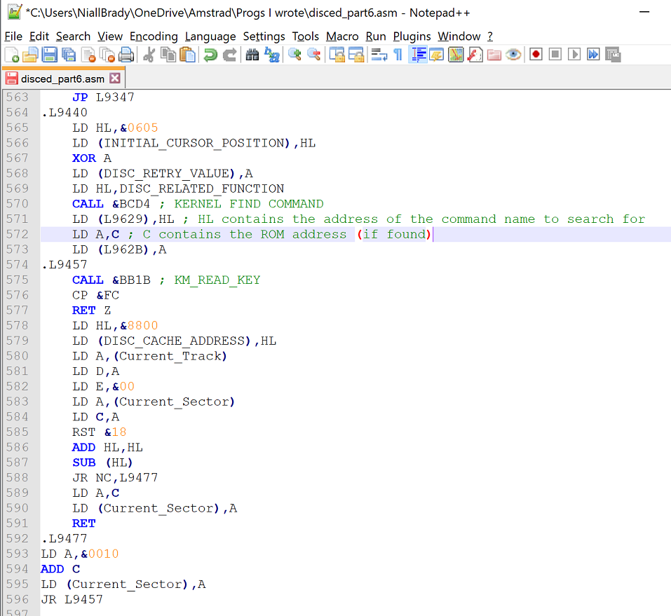
I also replaced all references to L9628 with DISC_RELATED_FUNCTION as I see I used before calling &BCD4 later in the code, and that firmware call is to find a ROM command.
As these blocks of code are called right at the beginning of the program I’ll label them DISC_INIT_X, so here’s how it looks now.
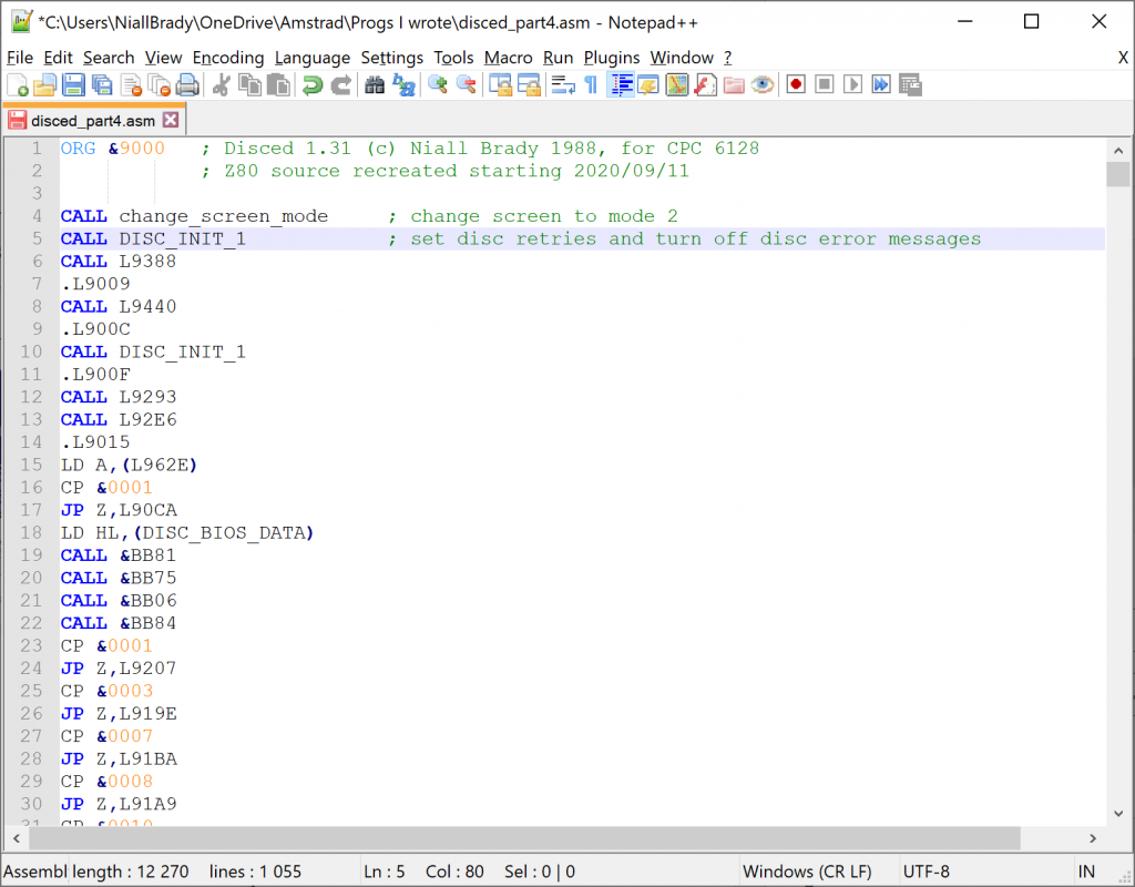
and the very start of Disced looks like this now.
Update !
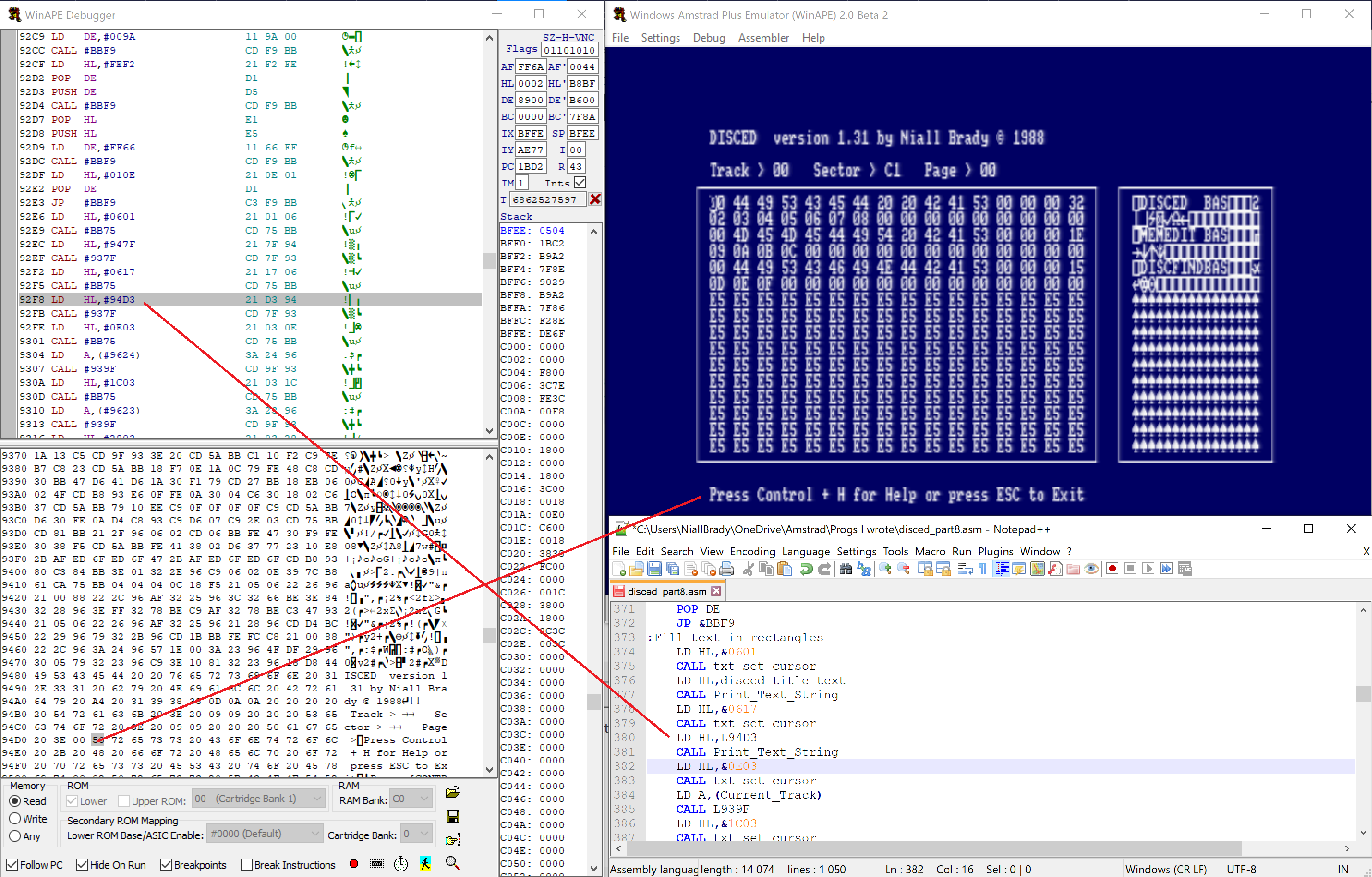
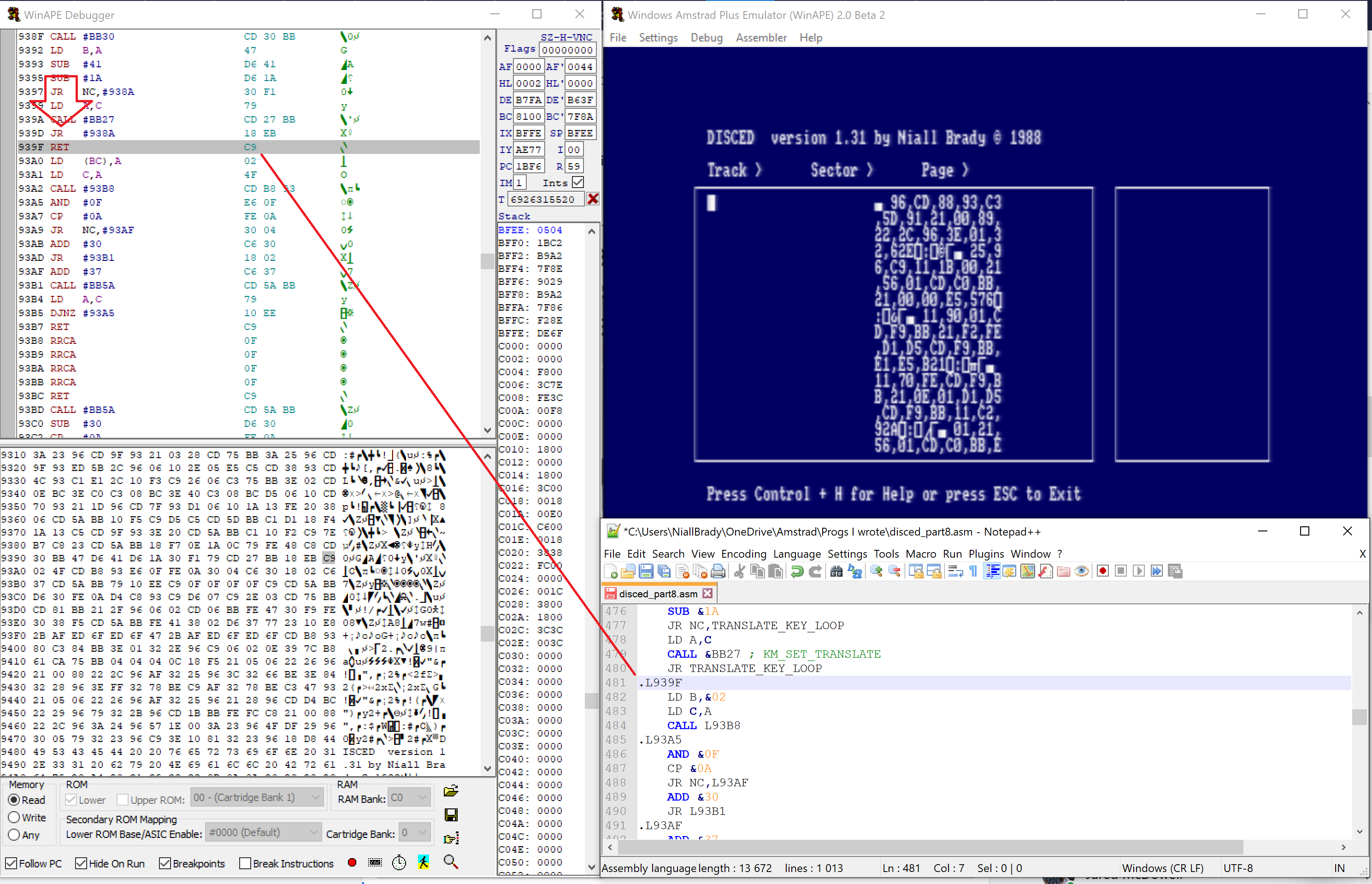
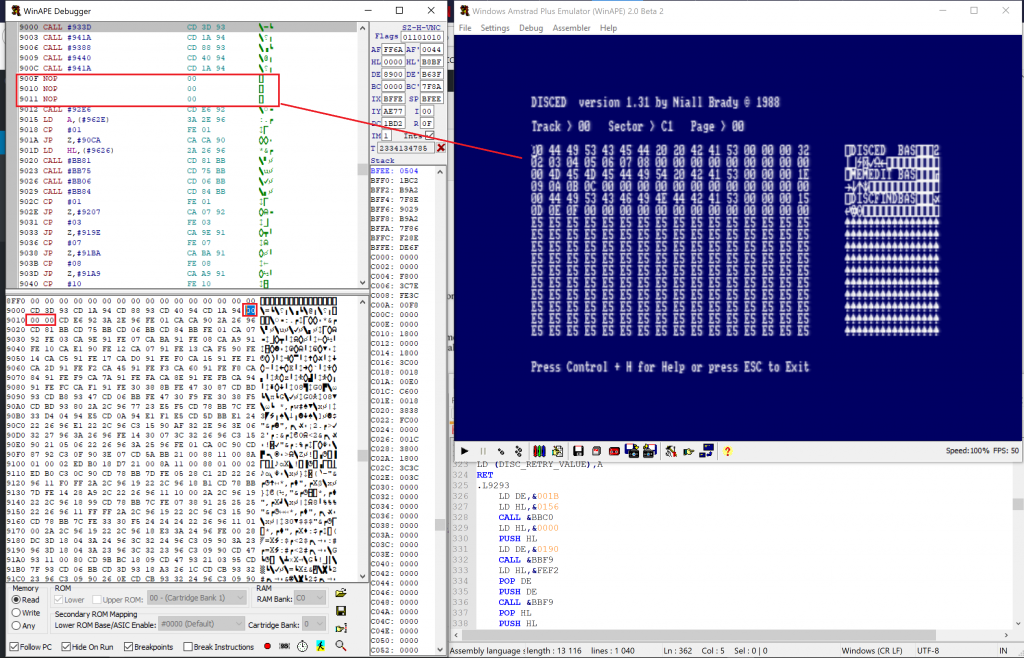
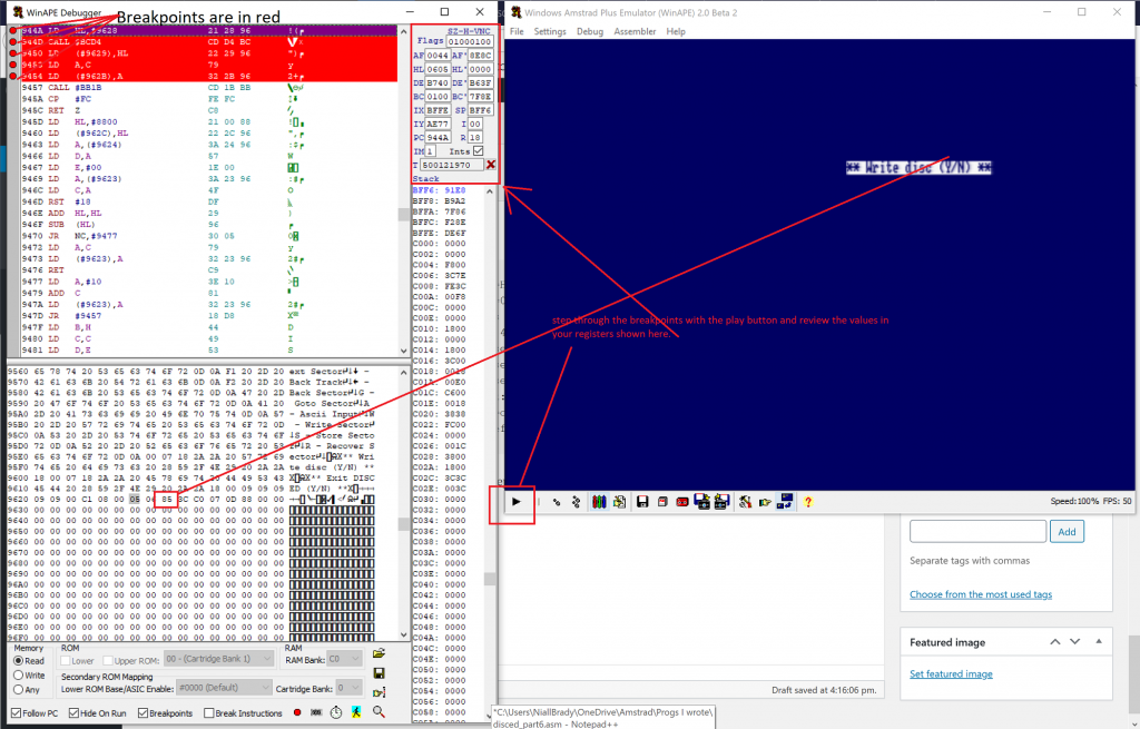
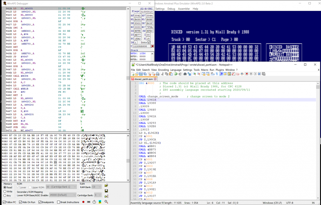
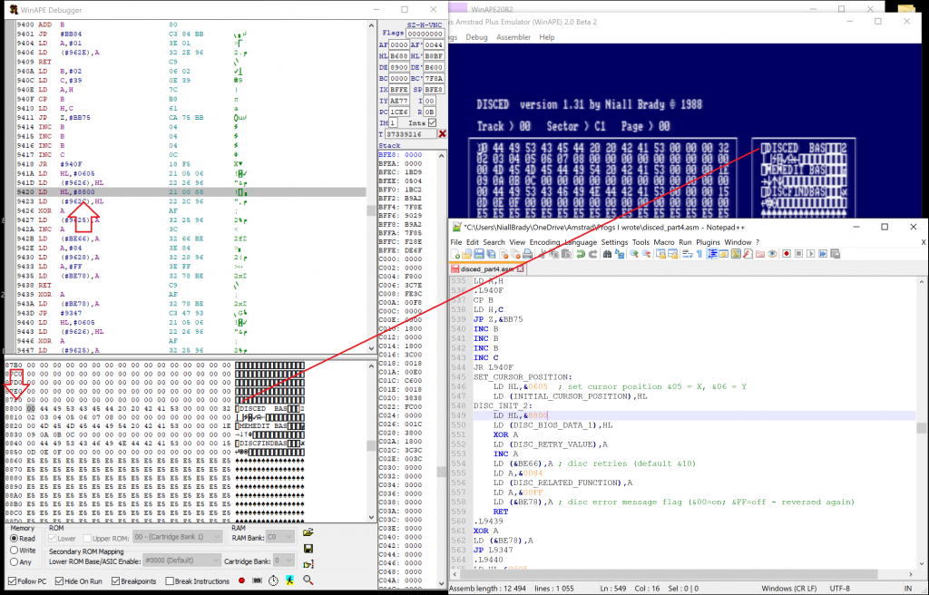
I had the WinAPE disassembler still open after submitting this blog post and I assumed I was done for the day, but the &05 &06 values still had me curious, so I decided to play around with them, hacking the values just like back in the day to see if I could figure what they were for.
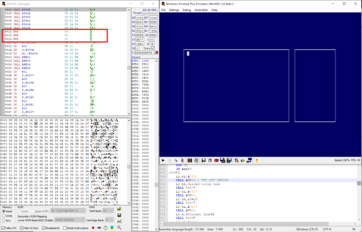
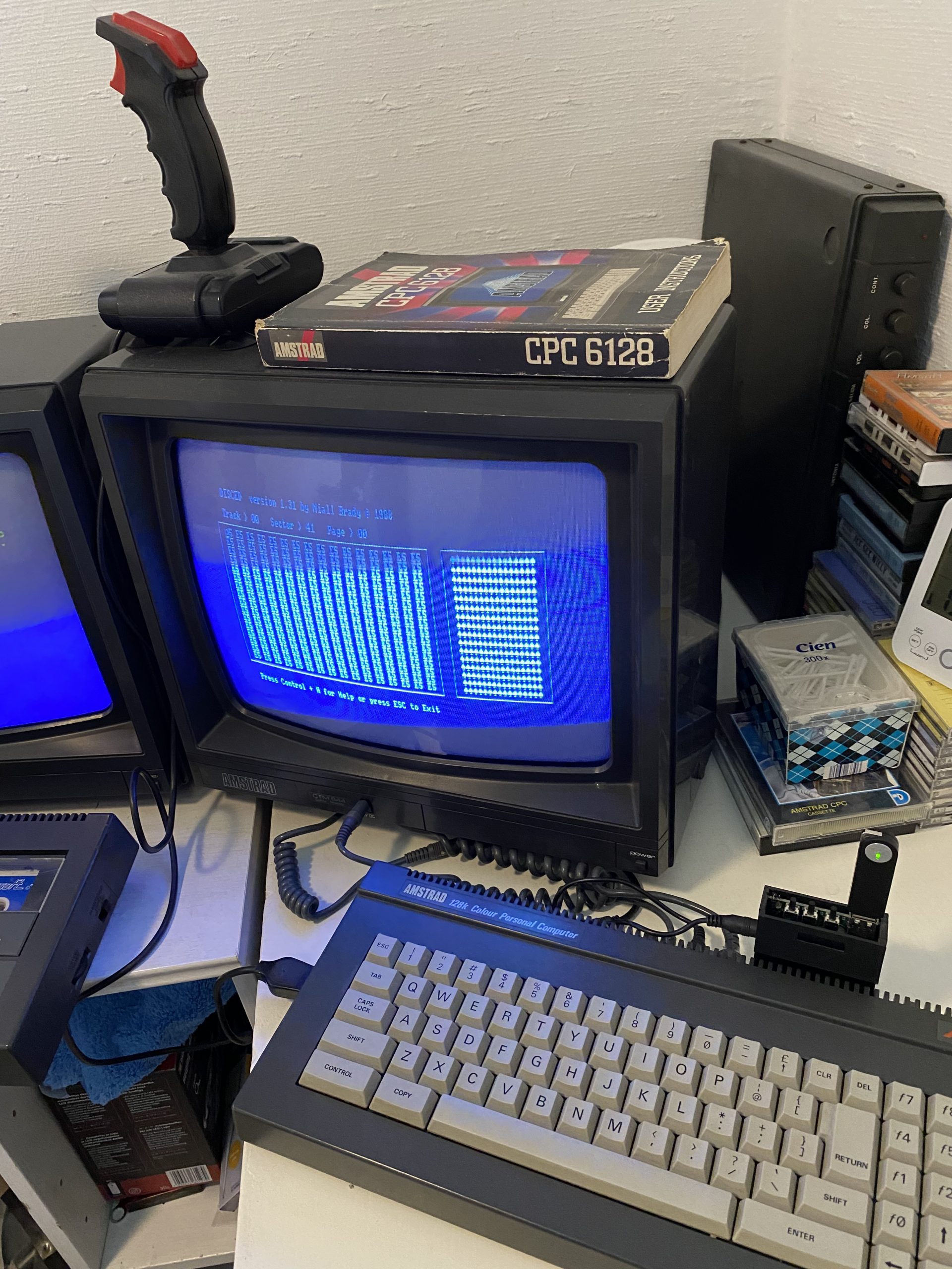
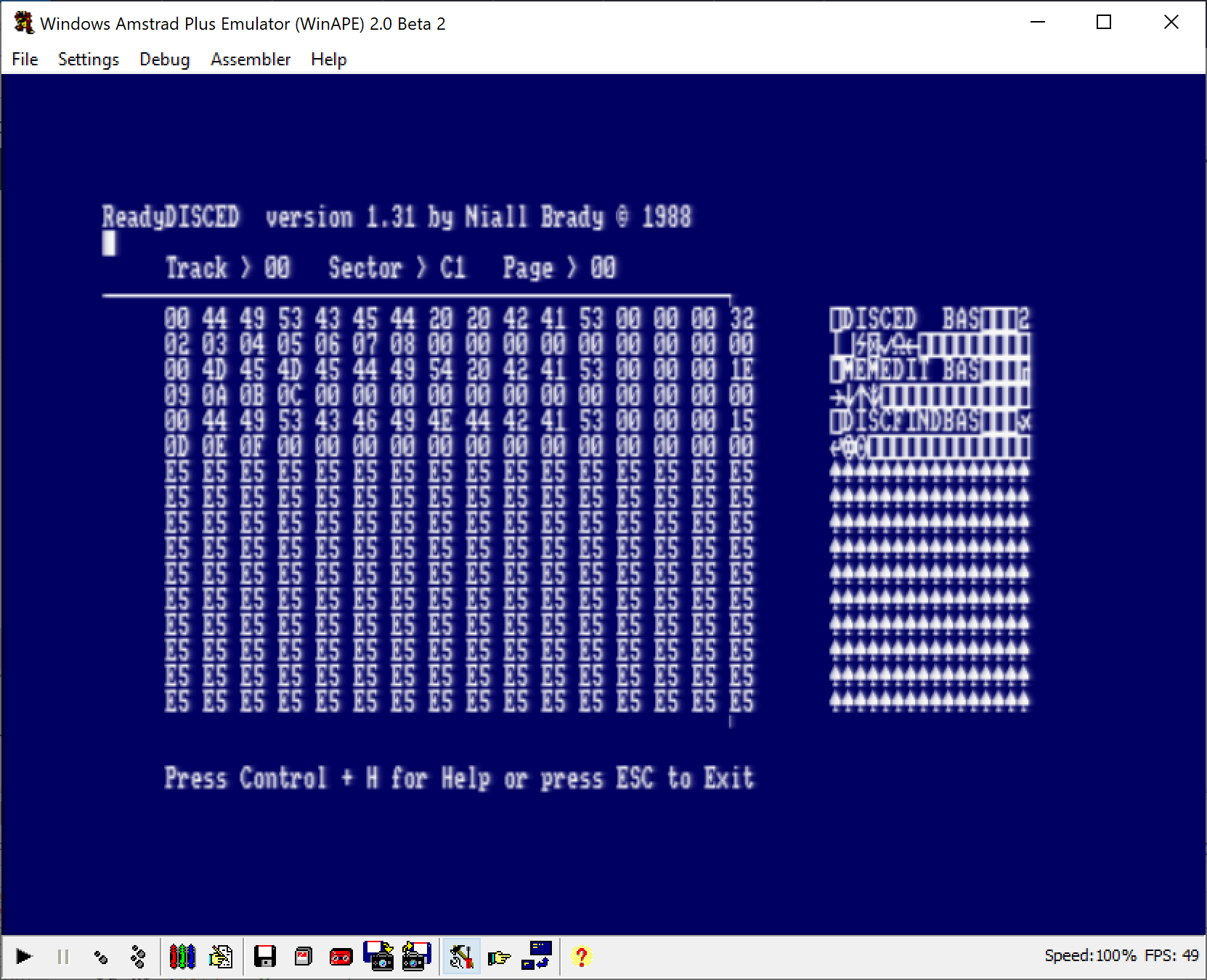
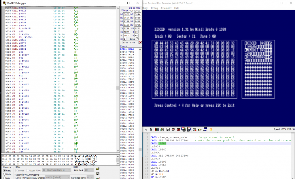
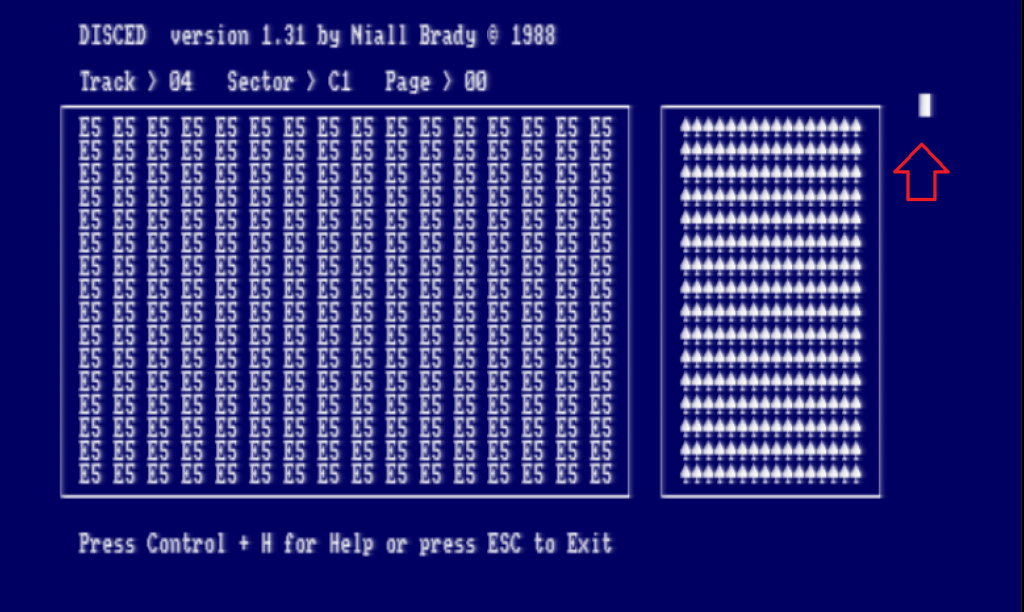
And what I found was interesting, here’s what Disced looks like normally.
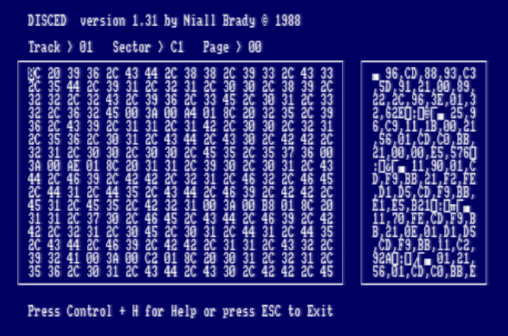
Notice how the moveable cursor is sitting in the Hexadecimal window pane on the left, and positioned on the first character there. I then changed &05 and replaced it with &01, to see what would happen.
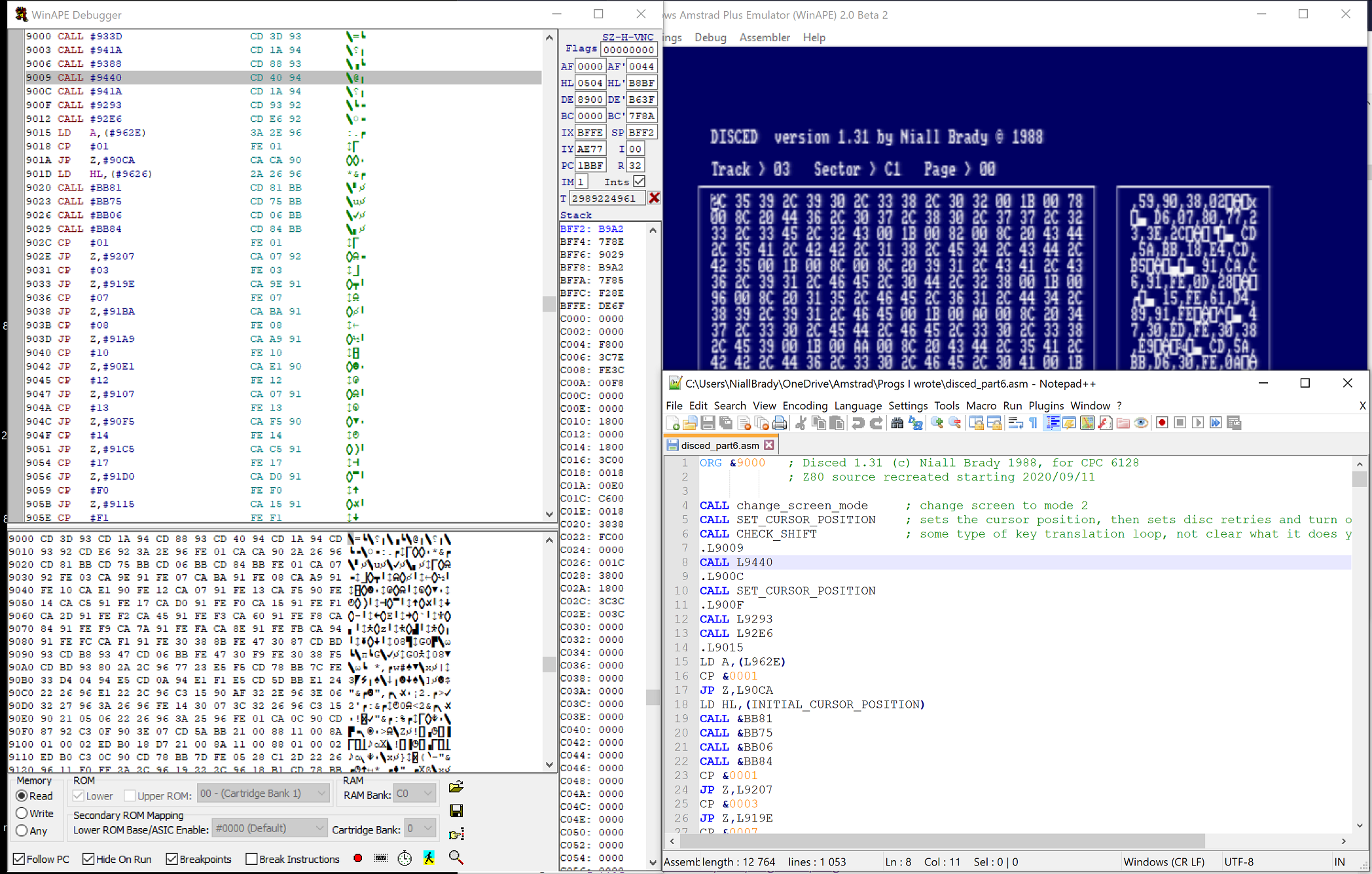
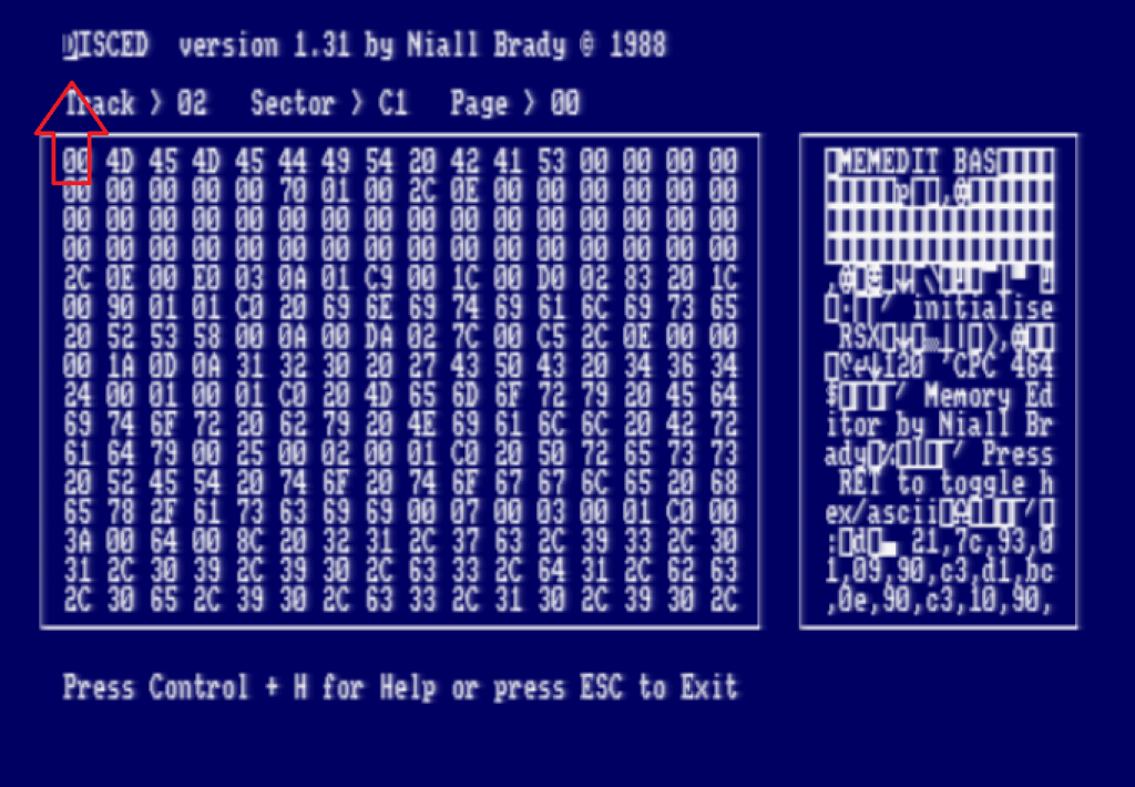
then I closed that window (the disassembler view) and went back to Disced. Nothing changed, so I pressed Ctrl + Up arrow in Disced and it browsed to the next track, at that point it updated the UI and I could see a change, the cursor had moved up !
So that got me excited, I next changed the value to something bigger, like &08 and lo and behold it has moved the cursor down.
So at this point I’m certain that the &05 value tells Disced where to put our moveable cursor in relation to the X axis.
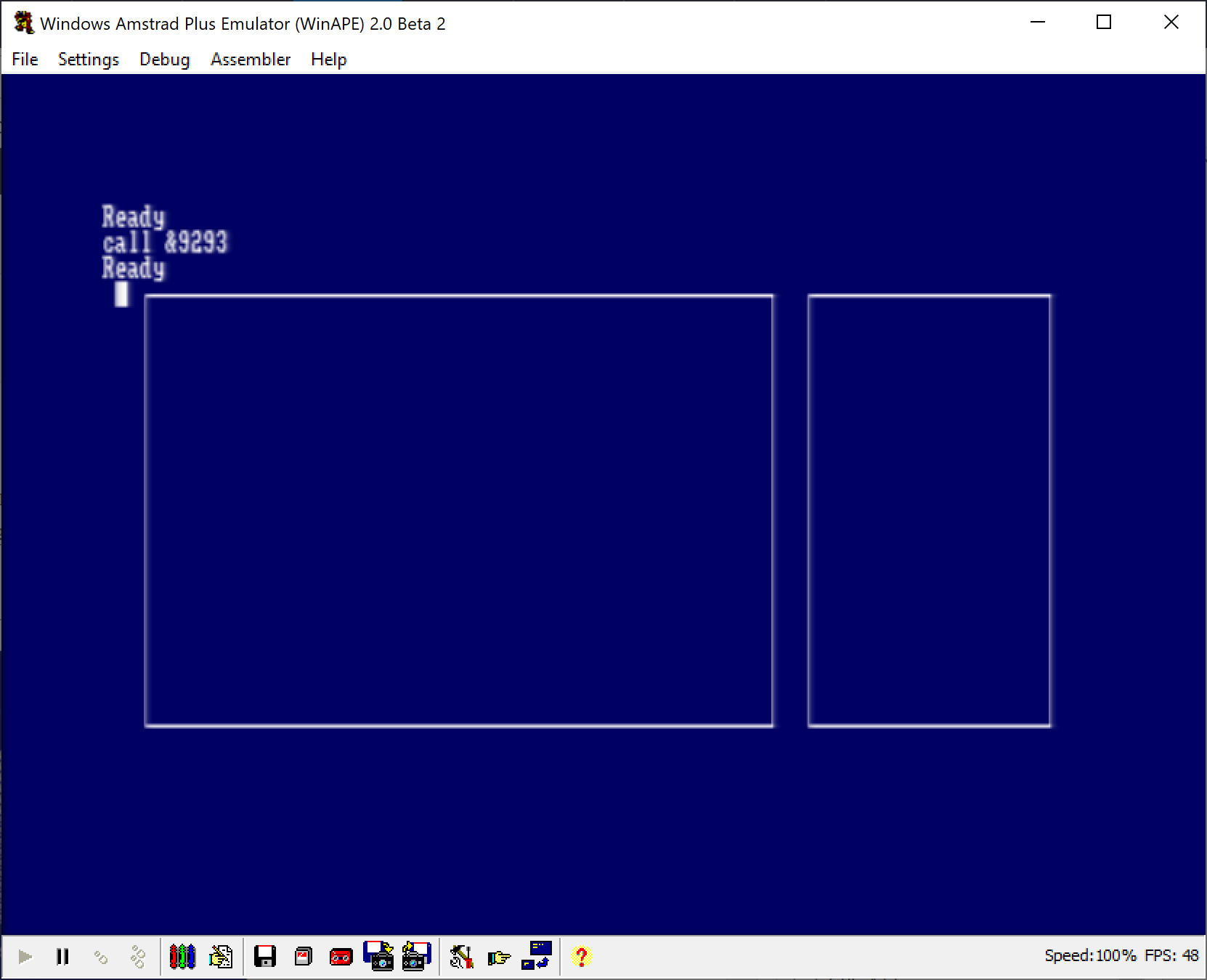
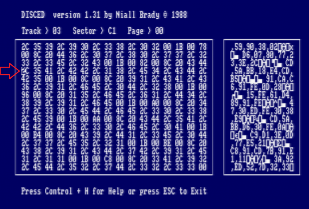
But what about the other value (&06). I reset &08 back to &05 and changed &06 to &00, and look at the result of that change !
So armed with that knowledge, I now know that the &05 &06 values are for defining exactly where I want the cursor to appear in my program !
I modified the Source Code to correspond to that new knowledge. After doing that, I set about hacking the other HL value of &88 &00, and I discovered that that address is where the contents of the disc being read are cached in memory, and any edits are stored in the cache and not directly on the disc.
Disced allows you to do it this way, you actually have to commit the changes in memory to the discs sector using CTRL+W. This saves you from destroying data on discs accidentally.
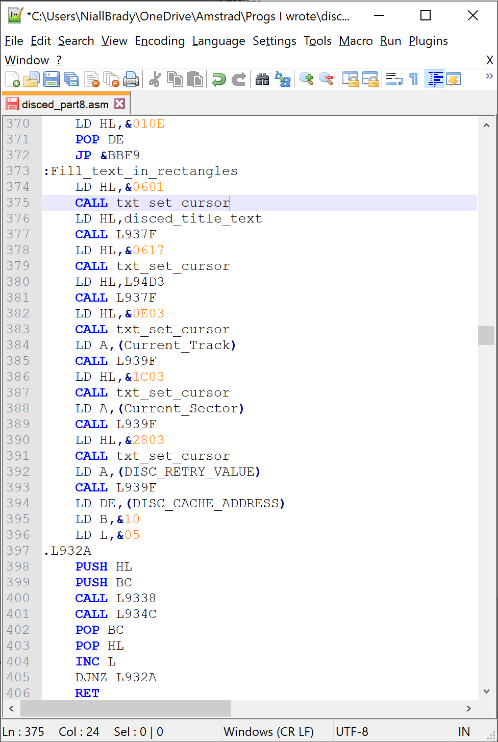
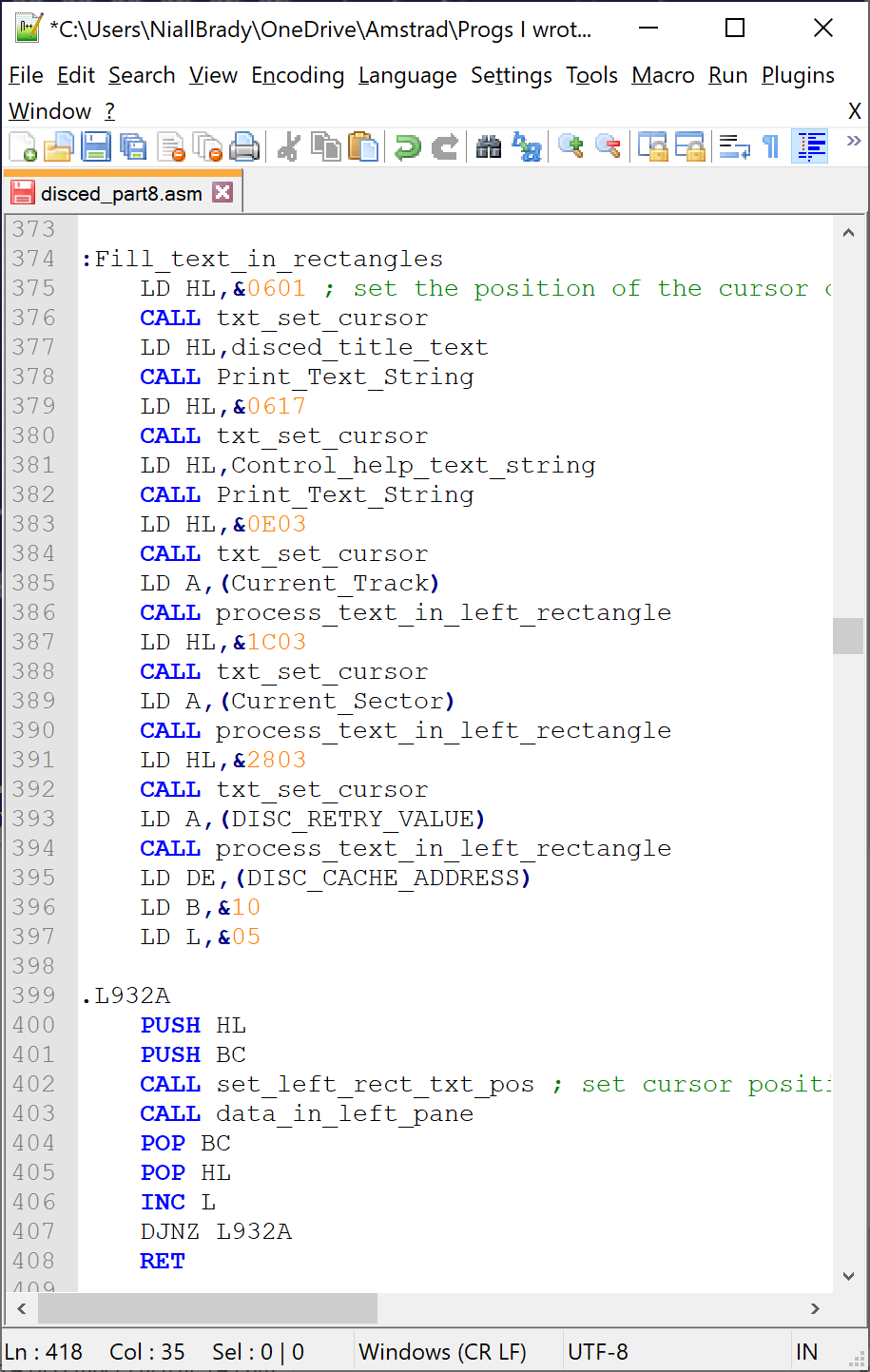
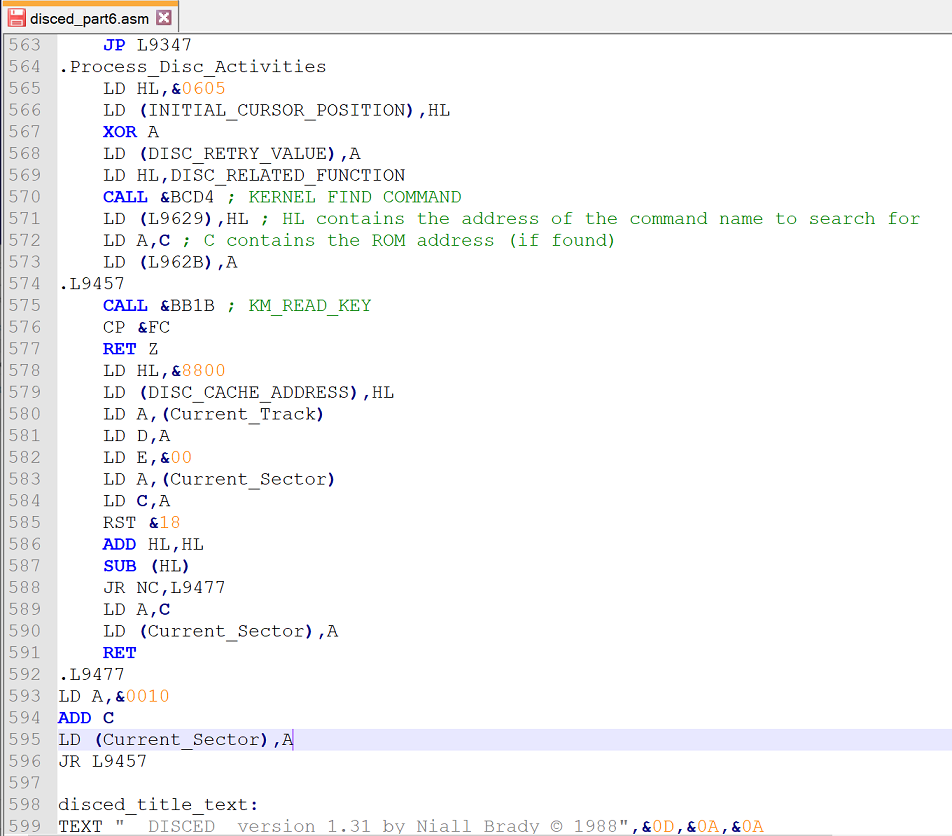
Awesome ! So after modifying the source code with my new found knowledge the little block of code now looks like this.
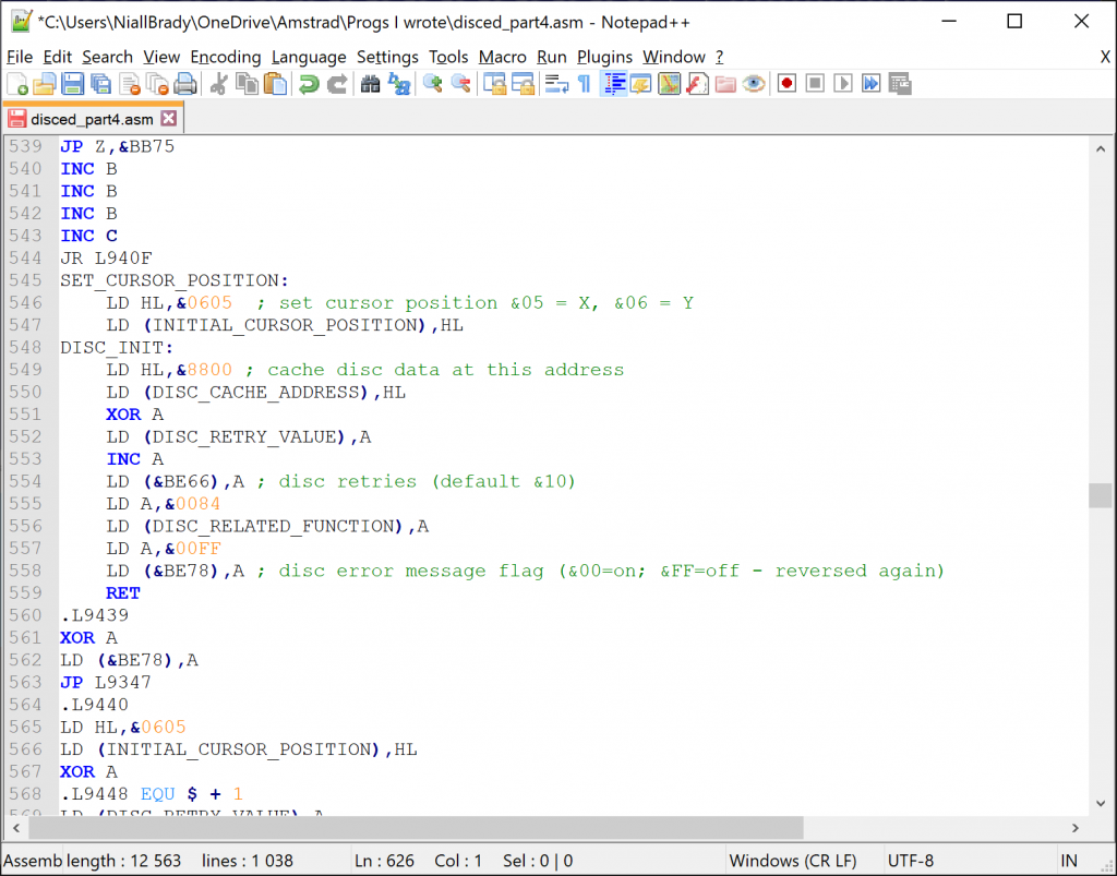
That’s it for this part, see you in Part 5.
Recommended reading

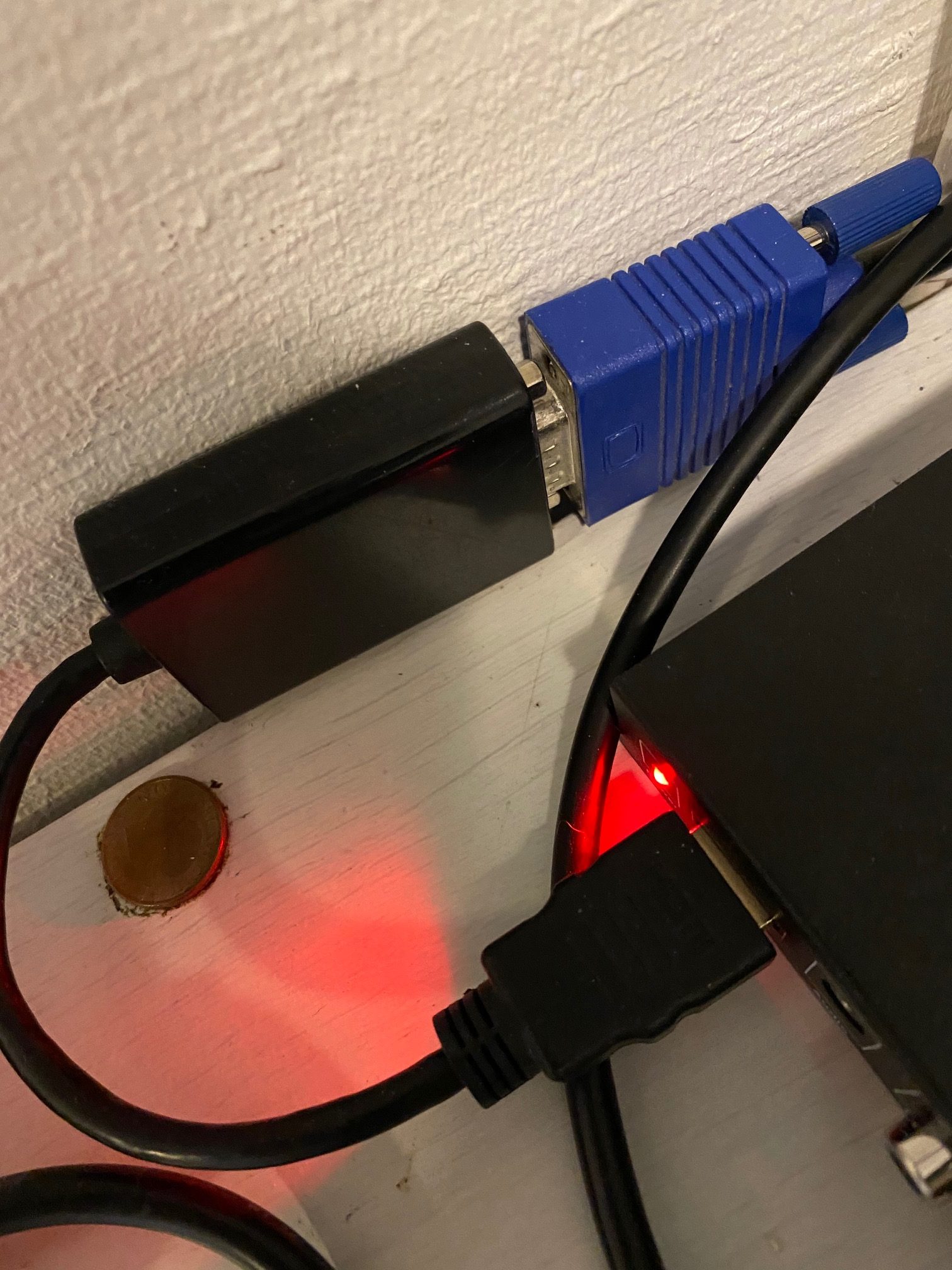
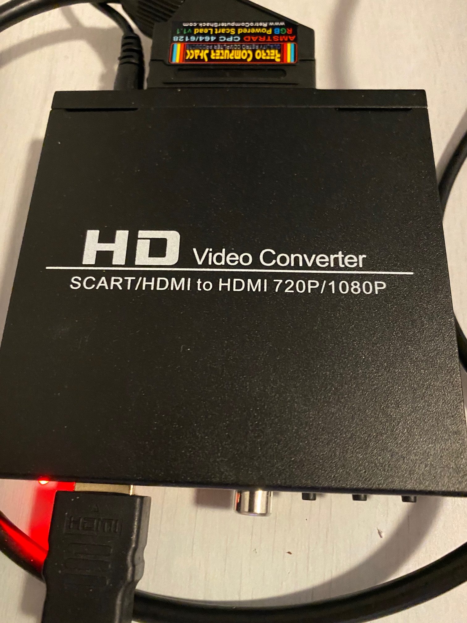
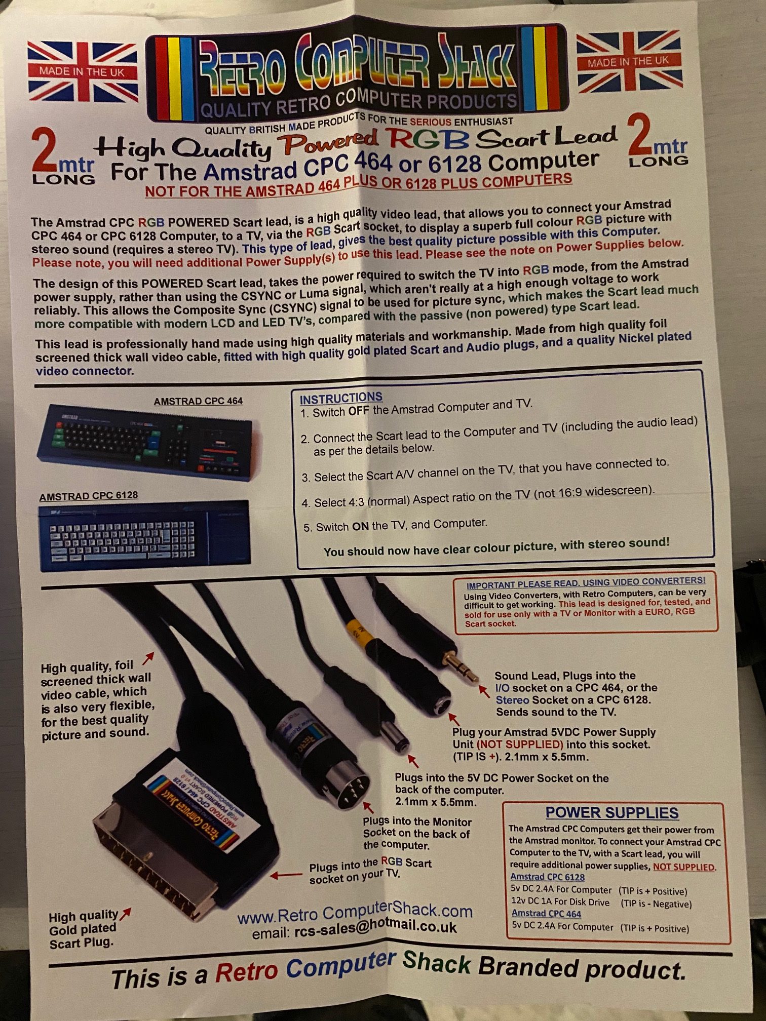
 The SCART Cable TV Video Lead
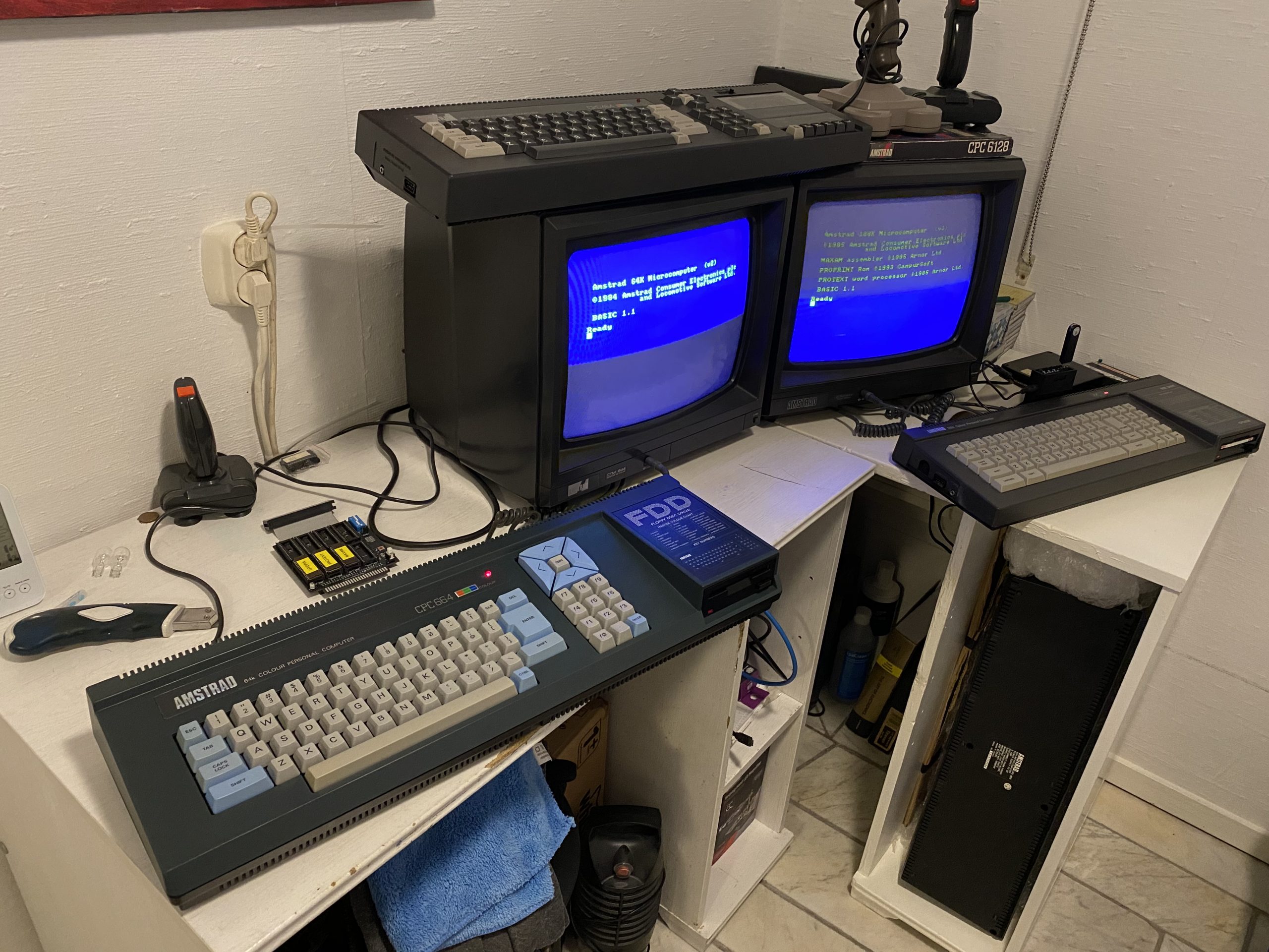
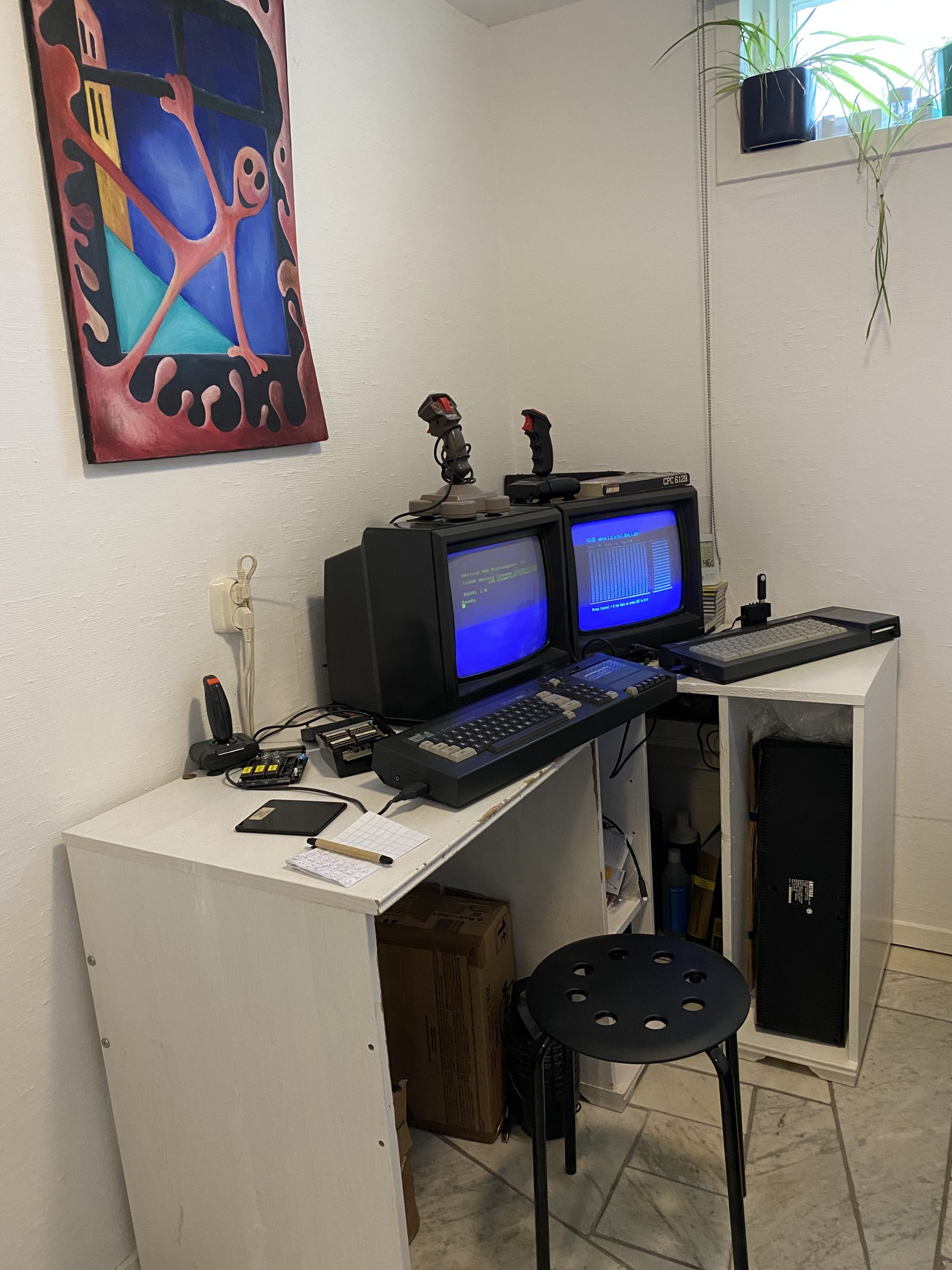
 After connecting everything up I was pleasantly surprised to see it working immediately. I was relieved !
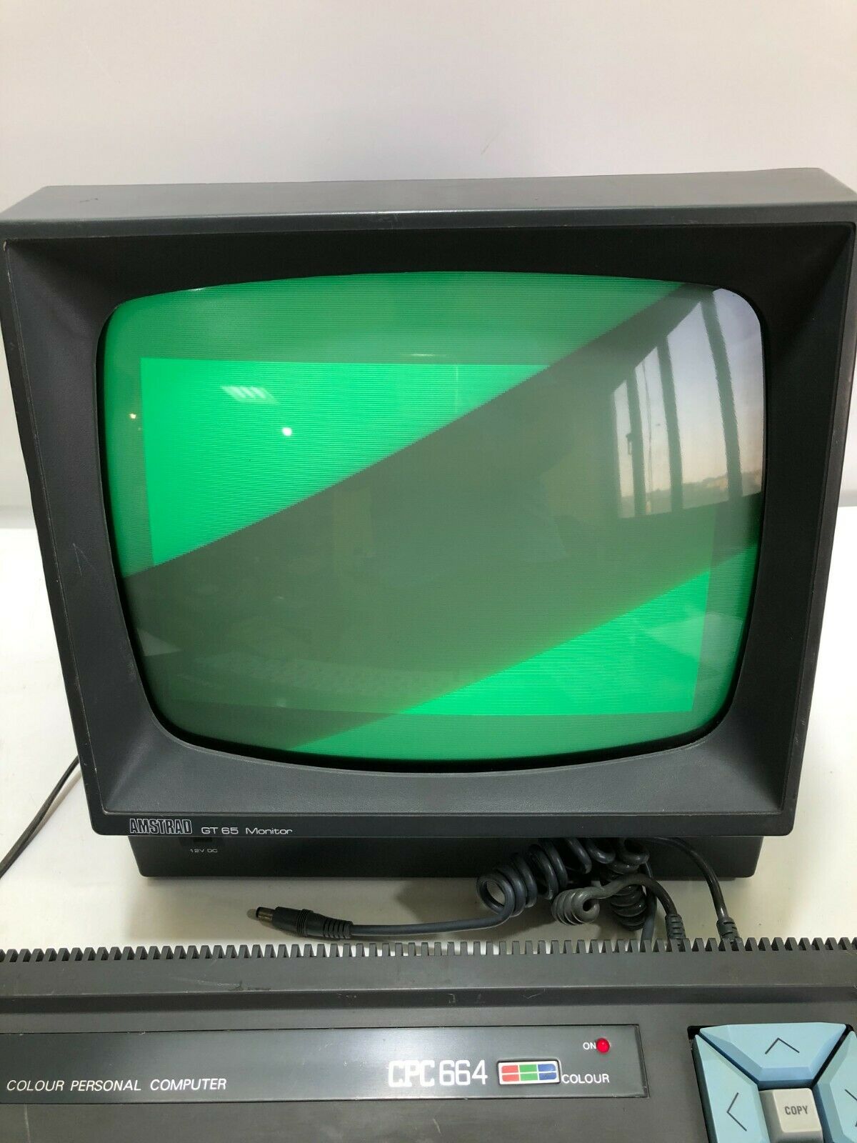
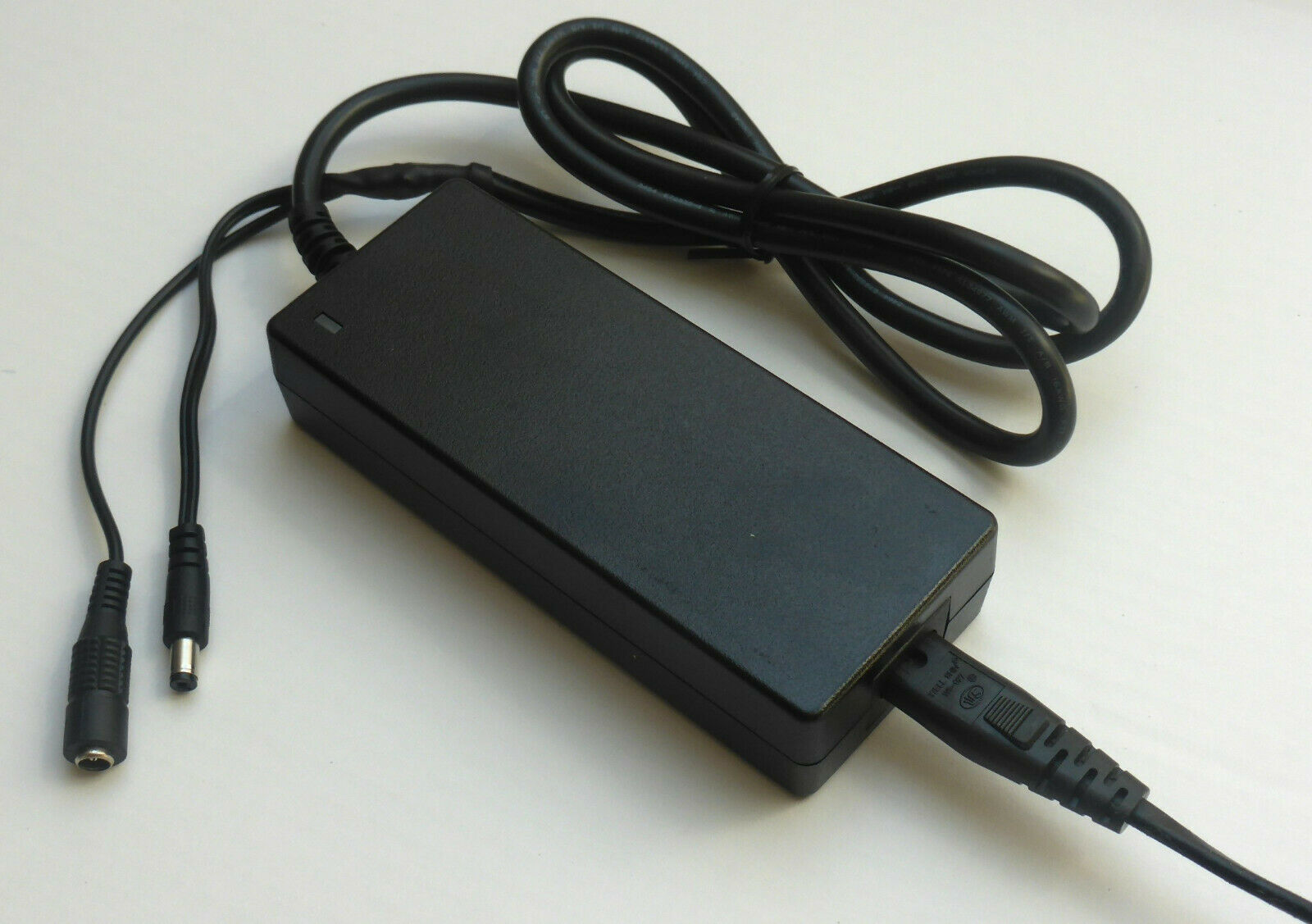
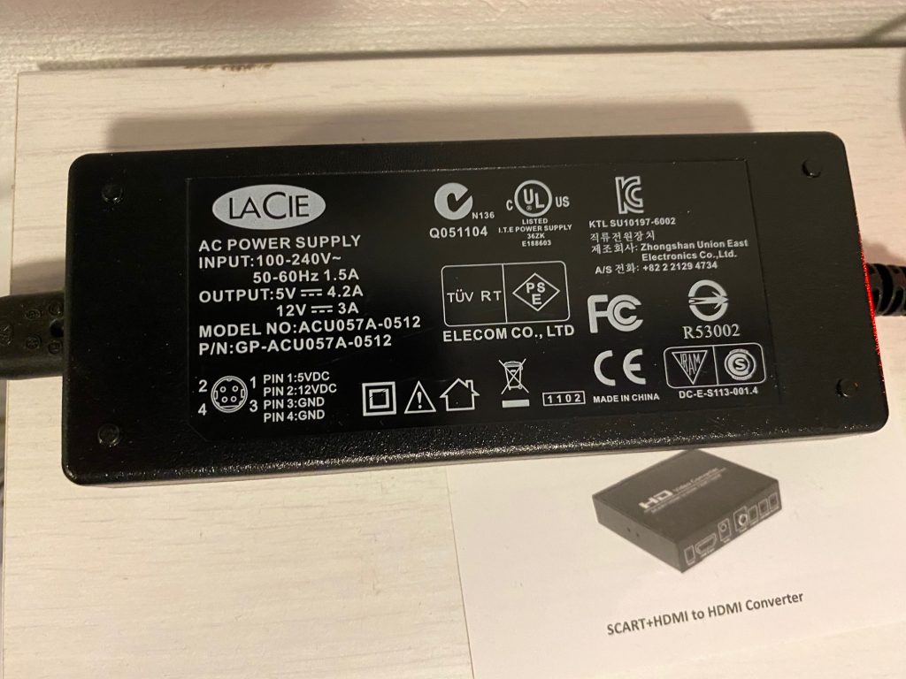
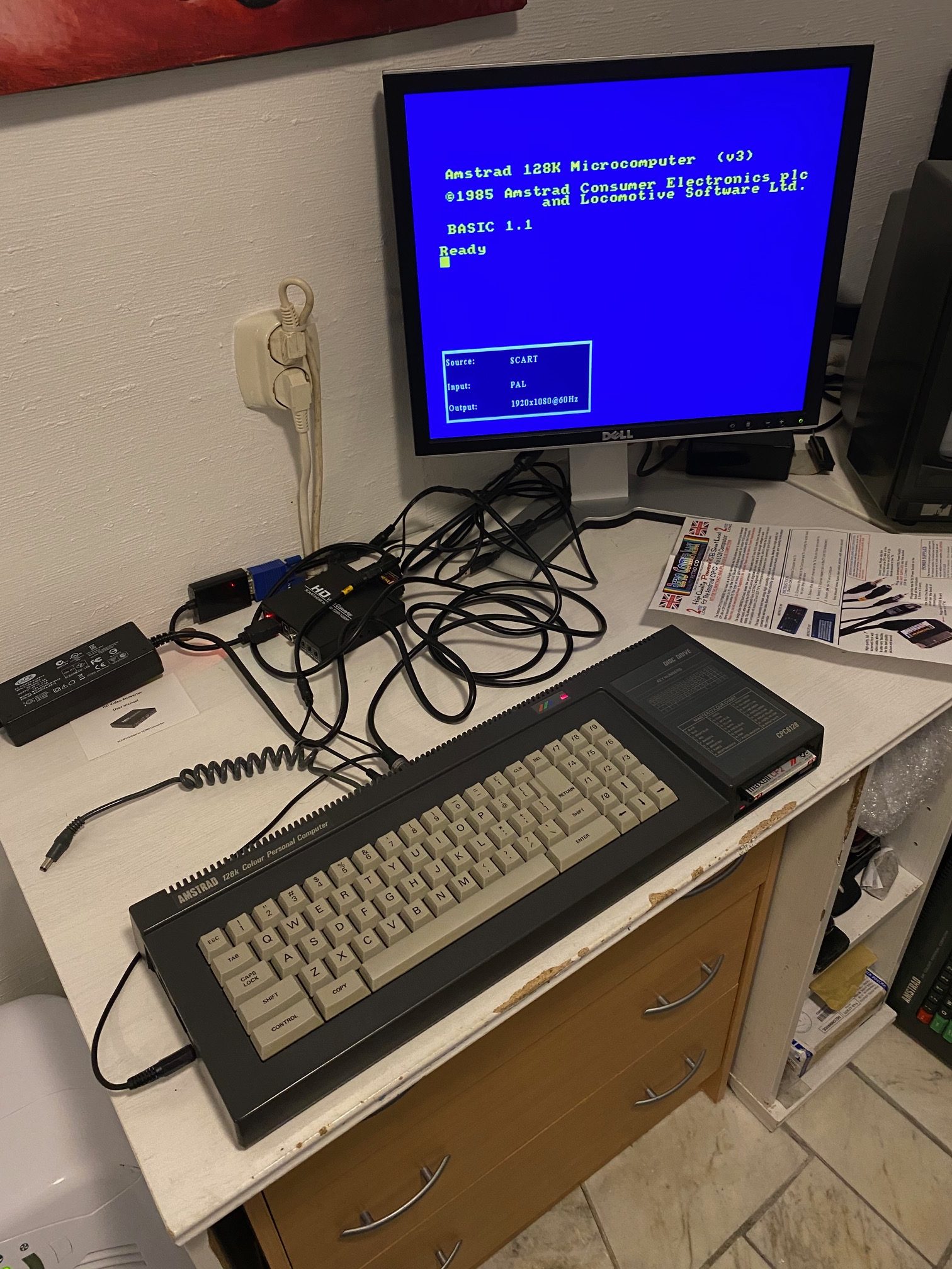 It’s very readable on the LCD and feels nice to look at. Next I connected up the 12v line and tested the FDD, it works as you can see here (I loaded up Alex Higgins pool world).
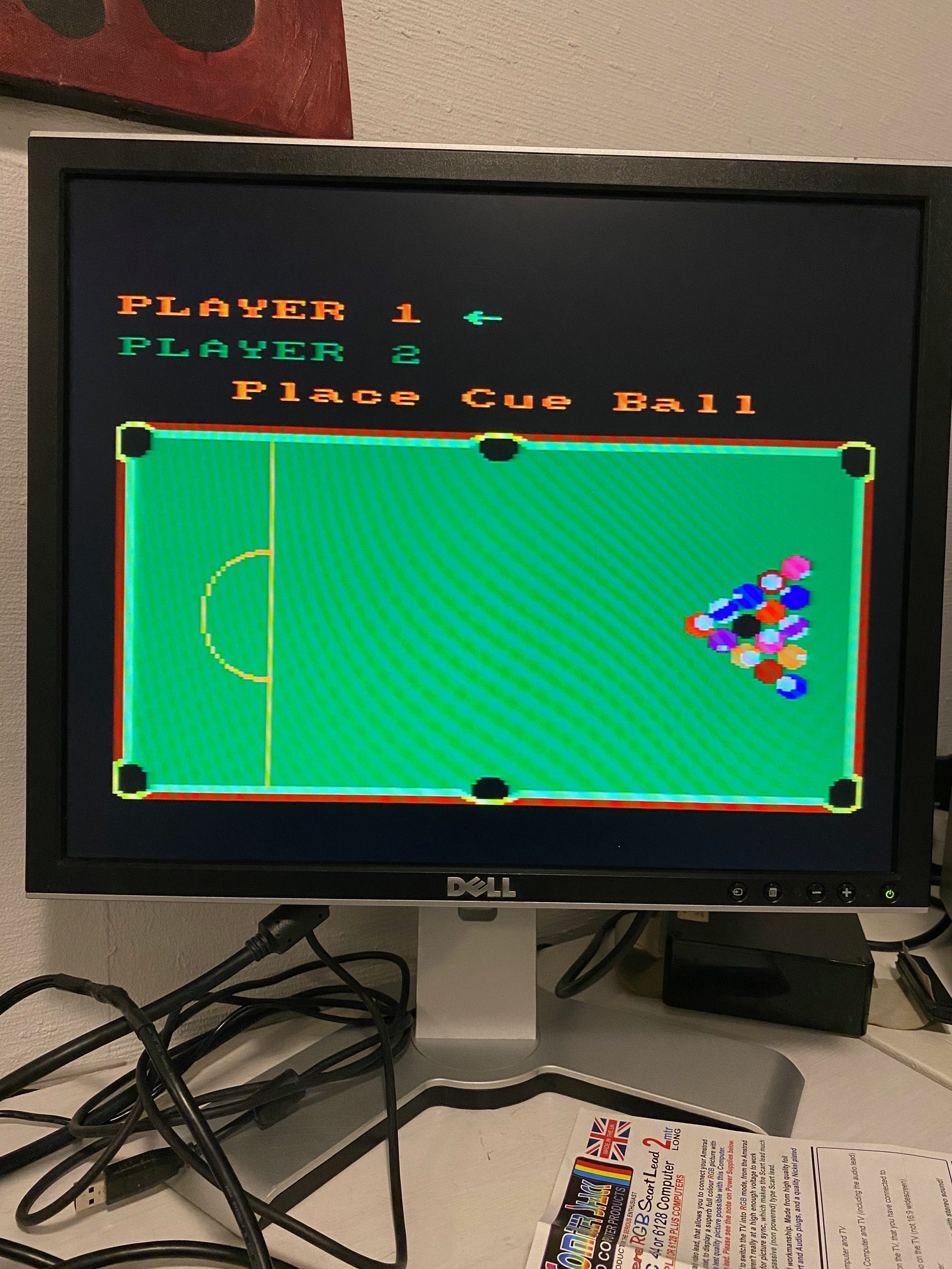 So all in all I’m very pleased with my new setup, I’ve loads more space for my CPC’s and this gives me new possibilities !